

(Estimated reading time: 14 minutes)
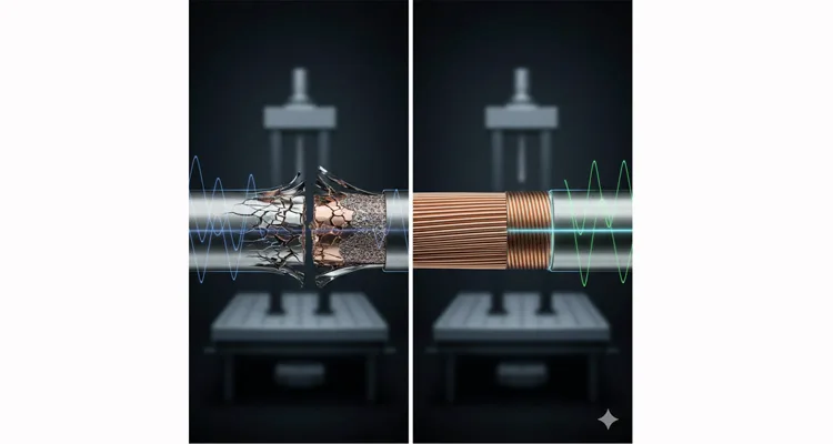
Forget the conference room whiteboards. On the failure analysis bench, where we dissect harnesses from harvesters and haul trucks, the solder-versus-crimp debate isn’t theoretical—it’s etched in fractured grain boundaries. This isn’t about preference; it’s a binary outcome dictated by metallurgy. One method engineers a time-bound failure; the other, when executed to a controlled protocol, engineers it out.
With twenty years spent decoding why connections fail, I can tell you: the 40x life differential isn’t marketing. It’s the inevitable physical consequence of choosing between a heterogeneous, heat-damaged composite and a homogeneous, solid-state union.
If your responsibility includes J1939 network uptime, OBD2 diagnostic certainty, or any system where a flickering signal costs thousands, this is the evidence you need. We’re moving past brochure claims to the raw data from our vibration shakers and scanning electron microscopes.
The Diagnostic Black Hole: Where Logic Leads to Wasted Weeks
The sequence is deceptively rational. A combine’s header control becomes erratic. A haul truck’s engine mysteriously derates. The diagnostic port streams J1939 communication errors—timeouts, missing ECUs. The engineer’s instinct, honed by complexity, points to software glitches, sensor faults, or the spectral culprit: EMI.
This initiates the black hole: 20 to 40 man-hours consumed re-flashing controllers, swapping modules, and conducting electromagnetic interference witch hunts. All this activity orbits around—but never lands on—the actual fault.
The breakthrough is often brutishly simple: a technician’s elbow bumps a wiring loom. The fault triggers instantly. The issue wasn’t electronic; it was mechanical fatigue at a termination point. But why does a soldered joint surrender in one season, while a crimped counterpart endures for the machine’s entire service life? The verdict is delivered before the first vibration cycle even begins.
The Inherent Flaws: Why Solder is a Fatigue Catalyst, Not Just a Connection
To forecast a joint’s lifespan under duress, interrogate its birth. Soldering is a high-temperature phase-change process that implants three congenital defects in any dynamic environment:
The Deliberately Weakened Zone (The Annealing Effect):
The soldering iron’s thermal energy doesn’t stop at the solder. It migrates into the copper strands, annealing the crystalline structure at the joint’s periphery. This heat-affected zone (HAZ) is now a band of softened, recrystallized copper—the most pliable mechanical link, where cyclic flexural stress chooses to initiate its work.
The Engineered Stress Riser (Capillary Action & Rigidity):
Molten solder climbs the stranded conductors via capillary action, like water ascending a paper towel. It transforms a dynamically flexible cable segment into a fixed-end cantilever beam. All vibrational kinetic energy converges at the acute transition from supple wire to unyielding solder fillet—a classic and potent stress concentration point.
The Progressive Embrittlement Layer (Intermetallic Growth):
Over time and through thermal cycles, a brittle stratum of copper-tin intermetallic compounds (IMCs) crystallizes at the solder-conductor interface. This isn’t a bond; it’s a brittle interfacial layer—a microscopic, glass-like plane that fractures under repetitive loading.
A soldered joint is a rigid island in a flexible sea. It cannot comply with vibration; it resists until it ruptures. This is why intermittent faults—the signature of propagating micro-cracks—always herald a final, silent disconnect.
The Atomic Consolidation: How a Precision Crimp Achieves Monolithic Unity
Our crimping philosophy rejects mere compression. It is orchestrated metal flow leading to atomic-level consolidation. It operates through governed mechanical principles, not uncontrolled thermal chemistry.
Precision Deformation & Surface Preparation:
A geometrically calibrated die applies controlled, mega-Pascal level force. This force performs two critical actions: it first acts as a surface cleanser, plastically shearing and expelling oxides and organic contaminants, then drives the pristine, native copper of the terminal barrel and wire strands into complete, contaminant-free conformity.
The Solid-State Diffusion Bond (“Cold Weld”)
Under this intense, localized pressure, the crystal lattices of the two metals align at the atomic level. Atomic diffusion occurs across the now-flawless interface, forging a true metallurgical bond—a solid-state weld. Crucially, this occurs entirely below the recrystallization temperature of copper, resulting in absolutely zero heat-affected zone.
The Intrinsic Hermetic Seal:
The optimal deformation profile creates a permanent, gas-tight interface. With no pathway for oxygen or electrolyte ingress, galvanic corrosion is denied a foothold at the most critical point. This is non-negotiable. This effectiveness is grounded in a fundamental engineering principle: the gas-tight seal physically blocks the ingress of moisture and oxygen, which is central to reliable glass-to-metal sealing in harsh environments. It’s why our process is architected within an IATF 16949:2016 framework—valued not for the certificate, but for the PPAP documentation that specifies, measures, and archives every critical crimp parameter.
A properly executed crimp is a seamless, homogeneous material transition. Mechanical stress is distributed uniformly. Dynamic flexibility is preserved. The conductor and terminal respond to vibration as a single, unified entity.
The Data: A Brutal Test Protocol That Reveals Fundamental Truths
Speculation has no place here. We defer to the shaker table. Our validation regimen pursues the performance frontier, extending beyond the baseline of ISO 16750-3. In a controlled comparative high-cycle fatigue test (16 AWG wire, Deutsch DT contacts), we simulated the dominant second-order vibration of a high-torque diesel engine.
| Termination Method | Failure Threshold (Electrical) | Cycles to Failure / Test Suspension | Post-Mortem Metallurgical Analysis |
| Professionally Soldered & Strain-Relieved | Intermittent resistance spikes >10Ω (>1µs) – sufficient to corrupt a CAN frame. | 2.3 x 10⁶ to 1.0 x 10⁷ cycles | Fractography revealed crack initiation within the HAZ, with propagation through the brittle Cu-Sn IMC layer. This failure is a classic manifestation of fretting wear and corrosion, a primary damage mechanism for electrical connections under vibration. |
| Precision Crimped (Our Protocol) | Resistance variance remained within <0.01Ω baseline. No intermittent faults. | 1.0 x 10⁸ cycles (test suspended, no failure) | Cold weld interface remained fully intact. Cross-section showed uniform strand deformation and complete absence of voids. |
The >40x life multiplier is not miraculous. It is the inevitable arithmetic result of eliminating the three intrinsic failure vectors that soldering cannot avoid: the HAZ, the stress riser, and the brittle intermetallic layer. For the complete test methodology and decision matrices, our definitive resource, Crimp vs. Solder: A Vibration Reliability Guide, provides exhaustive evidence.
The Production Doctrine: Four Non-Negotiable Protocols
Adopting crimps is not a component swap; it is the adoption of a documented, data-verified system.
The Matched Die Imperative:
The terminal manufacturer’s crimp profile is a contractual specification. We employ their designated, metrologically-calibrated die sets. “Approximate” crimps create microscopic voids, fatally compromising the hermetic seal premise.
Strand-Level Conformance:
Strip length is held to a ±0.2mm tolerance. A single rogue strand outside the crimp barrel creates a localized stress concentration and can breach environmental sealing. This is the inaugural checkpoint in our 4-step quality inspection regimen.
The Force-Displacement Signature:
For mission-critical applications, we utilize servo-electric presses that log the complete force-displacement curve for every termination. A CPK > 1.67 is a continuous output, not an aspiration. This is the operational essence of IATF 16949—bestowing a data pedigree on every connection.
Dual-Function Acknowledgment:
The crimp is responsible for electrical permanence. The connector’s integrated strain relief architecture is responsible for mechanical load management. Neglecting either function guarantees the other’s eventual failure. Our J1939 90-Degree Right-Angle Cable is a physical testament to this symbiotic relationship in confined spaces.
Five Costly Engineering Misdiagnoses (Documented in Our Forensic Files)
These are not mere oversights; they are expensive diagnostic cul-de-sacs we routinely encounter and document.
Misdiagnosis 1: “Visual Conformance Equals Reliability.”
A crimp can be aesthetically flawless yet mechanically unsound. Conclusive validation demands a destructive pull test (failure must occur in the wire, not the crimp) or metallographic cross-section analysis.
Misdiagnosis 2: “Interchangeability of Tooling.”
Employing a generic crimp tool with a precision terminal is an exercise in hope. The cold weld phenomenon is predicated on a geometrically precise, matched system.
Misdiagnosis 3: “A Standard Harness is Adequate.”
Off-the-shelf materials succumb to specific agents. Agricultural glyphosate, road de-icing salts, and petroleum-based fluids necessitate chemically specified seals and jacketing, a subject explored in our guide on J1939 Cable for Agriculture.
Misdiagnosis 4: “Connector Housing is a Substitute for Terminal Retention.”
The terminal’s primary latch secures the wire. The connector’s secondary locking mechanism secures the terminal itself. Omitting this step allows vibration to gradually “walk” the terminal from its cavity.
Misdiagnosis 5: “Attributing Intermittency Solely to EMI.”
A substandard crimp can disrupt 360° shielding continuity, inviting noise. However, the root cause is often a wildly fluctuating contact resistance that perfectly mimics EMI symptoms. Chasing the phantom of interference while ignoring the mechanical root is a costly detour, a principle explained in our CAN Bus EMI Shielding Guide.
The Validation Trinity: Moving from Faith to Fact
Abandon presumption. Embrace verification through this tripartite evidentiary standard:
1. Destructive Pull Test:
The assembly must meet or exceed SAE/USCAR-21 tensile force specifications. The only acceptable failure mode is fracture of the wire conductor outside the crimp zone.
2. Microsection Analysis:
This is the forensic gold standard. It is the sole method to visually confirm the cold weld—revealing uniform grain flow, absence of voids, and complete strand consolidation.
3. Crimp Force Monitoring:
Real-time, graphical representation of every crimp’s force profile. This is IATF 16949 and ISO 9001 translated into action, converting procedural hope into immutable process data.
Vibration Reliability Termination: From Diagnostic Bay to Hostile Environment
The cold weld is not an added feature; it is the non-negotiable substrate of our design philosophy.
- For unwavering diagnostic integrity, our OBD2 Extension Cable is built on this foundation, ensuring the diagnostic tool—never the cable—is the limiting variable.
- Within safety-critical J1939 networks, where a single fault can cascade, every termination in our 9-Pin Pigtail Breakout Cables is held to this exacting standard.
- In applications demanding acute bends, our 90-Degree J1939 Cable integrates the crimp with a robust, connector-based strain relief system.
FAQ: Addressing the Pragmatic Questions from the Field
Q: “Our legacy designs have used solder for decades. Why reconsider now?”
A: Operational paradigms have shifted. Today’s system complexity and cost of unplanned downtime have rendered previously “acceptable” failure rates economically intolerable. What once defined a minor nuisance now directly impacts your Total Cost of Ownership (TCO) and Mean Time Between Failures (MTBF).
Q: “Is ‘cold weld’ a verifiable condition or a marketing term?”
A: It is a verifiable metallurgical state—but only under process control. The proof is in the data: demand crimp cross-section micrographs and crimp press force-monitor charts from a recent production lot. Our own PPAP documentation packages routinely include this evidence.
Q: “Doesn’t the crimping process mechanically damage the copper conductors?”
A: A controlled crimp plastically deforms strands into a consolidated, dense mass without severing them. An uncontrolled crimp (over-crimp) will shear strands. This dichotomy is precisely why statistical process control (CPK) and force monitoring are indispensable, not optional.
Q: “How is this crimp process linked to IATF 16949 certification?”
A: IATF 16949 mandates evidence-based process control. Our crimping protocol, with its monitored force curves, documented parameters, and resultant PPAP packs, is a direct embodiment of that mandate. The certificate validates the system; the control plans and production part approval data validate every output.
Q: “How does a crimped joint resist corrosion compared to solder?”
A: The gas-tight seal of a proper crimp is its primary defense, eliminating the electrolyte pathway needed for corrosion. For extreme environments, we augment this with noble metal platings (e.g., gold over nickel) and connector rear-body seals. Furthermore, our climate-controlled storage prevents component degradation before assembly.
Q: “What’s the path forward for existing equipment with soldered harnesses?”
A: For field repair, utilize qualified crimp-based splice systems. For harness redesign or replacement, frame it as a reliability upgrade—a mechanical analogy to migrating from a legacy J1708 network to a J1939 backbone.
Q: “Does the 40x life advantage apply universally across all vibration spectra?”
A: The magnitude of advantage is most pronounced in high-cycle, medium-to-high amplitude vibration (e.g., engine-mounted components). In low-frequency, high-displacement environments, crimps still prevail on fundamental principle: they lack the brittle intermetallic phases and stress risers that solder inherently creates.
Q: “What should a true supplier process audit entail, beyond checking certificates?”
A: Audit the evidence, not the framed documents. Require: 1) Crimp force monitor trend charts, 2) Destructive pull test data logs, 3) A sample PPAP package, and 4) A physical sample for your own cross-section analysis. This is the methodology we apply internally and is aligned with a rigorous J1939 Cable ELD Compliance Audit mindset.
The Engineering Verdict
The discussion is concluded by material science. For electrical connections in high-vibration environments, the aggregate evidence—from atomic bonding mechanisms, accelerated life testing, and forensic field analysis—renders an unequivocal verdict in favor of precision crimping. The solid-state diffusion bond (“cold weld”) is the definitive differentiator.
This principle is the immutable core of every high-reliability cable assembly we engineer. To explore its application against specific adversaries—from a combine’s high-pressure washdown to a forestry grapple’s relentless shock—our central guide provides the contextual framework for implementation.
Beyond the Part Number: Engaging an Engineering Partner
When you are confronting repetitive failures or architecting a new platform, you require more than a catalog SKU. You require a partner for whom reliability is designed and manufactured in, not merely inspected for at the end.
- For a technical consultation on your specific vibration profile and environmental challenges, initiate a dialogue directly via WhatsApp.
- To submit schematics or specifications for formal engineering review and PPAP planning, utilize our dedicated Engineering Contact Page.
We specialize in OEM-focused customization and engineering support, encoding the durability you require from the very first crimp onward.
