

I spent last Tuesday morning staring at an oscilloscope in a customer’s lab, watching a J1939 backbone that looked more like a heartbeat monitor than a clean digital signal. The glitches were random, the error frames were intermittent, and the engineering manager was ready to swap every node on the network. When you are deep in the weeds of diagnosing intermittent CAN bus failures, assumptions are expensive—and this one was about to cost him a harvest season.
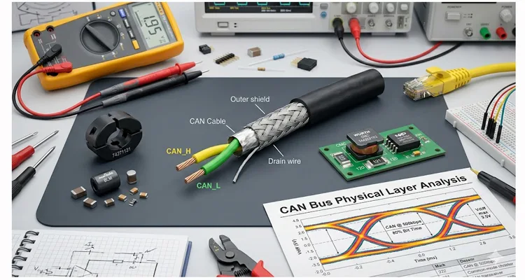
The culprit wasn’t the transceivers. It wasn’t the software. It was the assumption that “shielding” and “filtering” are the same thing. They are not. And using the wrong one—or using them in the wrong order—can turn a robust 500kbps network into a pile of retransmissions. The CAN bus protocol was designed to be resilient, but the physical layer—the wires, connectors, and terminations—determines whether that resilience holds up when a 200A motor kicks in.
If you are specifying components for off-highway vehicles or industrial controls, you need to know exactly where to place a ferrite bead, when a common-mode choke (CMC) is non-negotiable, and why a shielded cable can sometimes make things worse. We have published a practical OEM engineer checklist for EMI-hardened diagnostic cables that complements this discussion.
The 2:00 AM Call—When Good Hardware Goes Bad
A client in the agricultural sector called me in a panic last harvest season. Their combine harvesters were dropping the CAN connection to the GPS guidance module, but only when the main threshing drum engaged. The cable run was about six meters from the cab to the rear implement.
They had already tried “heavy-duty” shielded CAN cable. The problem persisted.
When I pulled the data, the common-mode voltage on CAN_H and CAN_L was spiking over 10V relative to ground during the engagement. The transceiver (a standard 1040-type) was going into protection, shutting down the bus.
We weren’t dealing with a simple radiated noise problem. We were dealing with a ground potential shift caused by a high-current motor starting up. The shield on their expensive cable was acting as an antenna for this ground noise, coupling it directly into the signal pair. This scenario is more common than most realize; we documented a similar mining welding interference case study on J1939 shielding where ground shifts crippled a network—and it took three weeks to convince the site engineer that the shield was the problem, not the solution.
The Physics of Interference (A Short, Practical View)
To fix this, we have to separate the noise into two distinct flavors:
Differential Mode Noise
Think of differential noise as an argument between the two wires—they disagree on voltage, so the signal gets confused. Honestly, CAN is pretty good at rejecting this naturally because of the twisted pair. The geometry does the heavy lifting here: every twist couples the wires to each other and cancels out externally induced fields.
Common Mode Noise
Common-mode noise is the silent network destroyer. This is noise that appears identically on both CAN_H and CAN_L relative to ground. Transceivers are built to reject common-mode noise—that is literally what “common-mode rejection ratio” means. But every silicon chip has a breaking point. If the voltage climbs outside the typical -7V to +12V range, the silicon latches up or fails entirely. And here is the problem most application notes skip: common-mode noise turns your nice twisted pair into a transmitting antenna, broadcasting interference back into the environment.
Understanding the root sources helps. We have analyzed various EMI sources from VFDs to CANbus diagnostics that generate these exact noise patterns—often traced back to poor grounding or lack of filtering at the source.
Here is where the tools differ.
| Solution | What It Actually Targets |
| Shielded Cable | Radiated EMI from external sources |
| Ferrite Core | High-frequency common-mode noise spikes |
| Common-Mode Choke | Persistent conducted noise on the lines |
Shielded Cable
I think of shielded cable as wrapping your data in a metal blanket—external noise hits it and drains to ground instead of corrupting your data lines. It is a two-way street: outside interference stays outside, and your own signal noise stays contained. It is excellent for protecting against capacitive-coupled noise (like nearby AC power lines or radio transmitters). However, a shield does nothing to stop low-frequency ground loops. In fact, if you ground the shield at both ends, you create a ground loop, which injects low-frequency hum directly onto your signal ground. For a deeper dive, our field guide on CAN bus EMI shielding covers the nuances of shield termination—especially the 360° termination we use on our overmolded connectors.
Common-Mode Choke (CMC)
If I had to pick one component that saves more field failures than any other, it is the common-mode choke. A CMC presents a high impedance to common-mode currents (the noise we hate) and a low impedance (essentially just the DC resistance of the wire) to differential signals (the data we love). It physically blocks the noise current from flowing. On a CAN bus, a CMC is the first line of defense against those nasty ground shifts and motor noise that crash networks in the field. According to Vector’s CAN transceiver tutorial, even with high common-mode rejection, a CMC near the output helps further reduce emissions in critical use areas—something we’ve confirmed in our own pre-compliance testing.
Ferrite Cores (Split Beads)
Ferrites are the mechanical filter of the EMI world—less elegant than a CMC, but they get the job done when space allows or when retrofitting existing equipment. They absorb high-frequency noise and dissipate it as heat. I typically see these used as a “band-aid” on an existing cable harness during troubleshooting. They work, but their performance is highly dependent on the material (43 material for noise suppression, 31 material for lower-frequency chokes) and the number of turns through the core. One turn might give you 100Ω impedance at 100MHz; two turns can quadruple that—but also add capacitance that might round off your signal edges if you go overboard.
A Step-by-Step Decision Matrix (How I Actually Spec It)
When I sit down to design a physical layer, I do not guess. I run through this checklist based on the environment.
Step 1: Put Eyes on the Problem—Don’t Assume
Before you order a single ferrite, clip on your differential probe and look at what the bus is actually doing. Switch your scope to AC coupling—this removes the DC offset so you can see the noise riding on top of your signal. Use the math function: (CAN_H + CAN_L) / 2.
- If you see slow sags or shifts (50Hz – 1kHz), you likely have a ground loop or power supply issue.
- If you see high-frequency bursts (1MHz+) when a relay clicks or a motor commutates, you have radiated coupling.
Step 2: The “No-Choke” Rule (TI’s Advice)
Modern transceivers (like the TI SN65HVD1040 or 1050) are actually designed to be pretty clean. They have slew rate control built in. If you are in a car cabin, away from high power, and your PCB layout is solid, you might not need a CMC at all. But—and this is a big but—if your bus leaves a protected enclosure (like going to a remote sensor on a tractor arm), add a CMC. I’ve seen too many “it worked on the bench” designs fail the first time they’re installed on a running engine.
Step 3: The CMC Placement
The CMC must go on the bus side of the transceiver, right at the connector. I always place it after the TVS diodes (if using unidirectional TVS) but before the rest of the world. We use the Würth Elektronik WE-CMB or Coilcraft 1210CAN series for this because their impedance curve peaks right in that 50MHz-100MHz range where most cable radiation happens—and they’re rated for the 500kbps to 1Mbps signals we typically run.
Step 4: The Shield Grounding Strategy (The Critical One)
If you decide you need shielded cable (because you are running parallel to a 400V traction inverter cable), only ground the shield at ONE end.
- Ground at the source (controller) end: This drains high-frequency noise to the chassis ground at the source.
- Float at the device end: This prevents ground loop current from flowing through the shield braid.
I have seen dozens of engineers ground both ends “just to be safe,” only to create a 60Hz hum that saturated the CMC and killed the bus. The interaction between connectors and termination methods matters; we compare crimp vs. solder for vibration reliability in termination in another guide—and the same principles apply to shield terminations.
Step 5: Split Termination for the Win
If your bus is long and you are fighting common-mode noise, ditch the single 120-ohm resistor. Use split termination.
- Put two 60-ohm resistors in series between CAN_H and CAN_L.
- Connect the center tap to ground via a 4.7nF capacitor.
This creates a low-pass filter for common-mode noise right at the termination point. The ISO 11898-2 standard specifies a main twisted-pair bus terminated at each end with a 120 Ohm resistor, matching the bus’s characteristic impedance—but it doesn’t forbid this split variant. I have seen this reduce common-mode voltage swings by over 50% on a test bench in a high-interference agricultural application, and it costs pennies to implement.
The 5 Most Expensive Mistakes I See
1. The Multimeter Lies: Why a “Beep” Doesn’t Mean Your Cable Works
You check the cable with a multimeter, it beeps, so it must be good. Wrong. A crushed cable can still have DC continuity but completely fail at 500kbps due to impedance change or a crushed dielectric. Physical layer integrity is critical; we explore cold weld vs. vibration arbitration in harsh environments—and the same attention to detail applies to every millimeter of the cable.
2. Star Topologies with Stubs
I have watched teams pinch pennies on cable routing, only to spend thousands debugging phantom errors. Those unterminated stubs create signal echoes that confuse every receiver on the network. A star topology might save 2 meters of wire but cost 20 hours of labor. The ISO 11898 standard allows stub wires of up to 30 cm—anything longer creates reflections that degrade performance. I’ve seen stubs over 2 meters cause complete network failure at 250kbps.
3. Ferrite on the Wrong Side
Clamping a ferrite core on the cable inside the metal enclosure. The noise is outside the box; the ferrite needs to be on the external part of the cable to catch the common-mode current before it enters your clean ground plane. I once watched a team spend a week adding ferrites inside a shielded cabinet, wondering why their emissions test still failed—the noise was already inside.
4. Ignoring J1939 Shield Requirements
SAE J1939-11 specifically calls for shielded twisted pair. J1939-15 (reduced cost) does not. Using a shielded cable on a J1939-15 network without adjusting the grounding strategy can actually increase radiated emissions because the shield acts as an unintended antenna. If you are dealing with compliance, our analysis of J1939 cable ELD compliance and audit failure covers these pitfalls—and the fines that can follow.
5. Oversizing the CMC
Using a huge common-mode choke meant for power lines on a CAN data line. This introduces too much leakage inductance, which distorts the sharp edges of the CAN signal and closes your eye diagram. Stick to chokes rated for high-speed data—typically those with less than a few hundred nH leakage inductance and impedance in the 50-100Ω range at 100MHz.
How to Know You Actually Fixed It
Do not just trust that the error lights turned off. Prove it with measurements.
Measure the Differential Signal
Look at the eye diagram on the scope. The “eye” should be wide open, with a clean crossing point and minimal overshoot. If the eye is closing, you still have a problem.
Monitor the Error Counters
Before disconnecting, read the TXERR and RXERR counters from the CAN controllers. If they are climbing, you have a marginal bus. A truly fixed bus will have zero incrementing errors over an hour of heavy use—including during the worst-case noise events.
The Bend Test
Wiggle the harness near the high-noise areas while monitoring the bus. If you see glitches, your shielding or filtering is not robust enough to handle real-world vibration. This is where our J1939 ArmorLink vibration-validated cable assembly has saved field deployments—the braid and overmold are designed to maintain contact even under continuous flexing.
The Hardware You Need (The Practical Specs)
We build cables that have to survive this math every day. You do not just need copper; you need a controlled environment.
The Cable
We use 22-24 AWG twisted pair with a shield drain wire, but the twist rate is critical ( >30 twists per meter). We pair this with overmolded backshells that provide 360-degree coverage to the connector housing, so the shield termination is continuous—no pigtails, no gaps. For agricultural applications specifically, we created a J1939 cable agriculture survival guide based on field data from actual harvesters.
The Integration
If your application is J1939 heavy, like an excavator or a fire truck, we often recommend integrating the common-mode choke inside the cable mold or the connector housing. This puts the filtering exactly where it needs to be—right at the point of entry to the ECU, before any noise can couple onto the PCB. Our guide on hardening OBD2 and J1939 for industrial EMI walks through similar integration strategies we’ve used with OEMs.
The Assurance
Every harness we ship is 100% tested for continuity and impedance. We run a 4-step quality inspection here in our climate-controlled facility, holding ISO 9001 and IATF 16949 standards. You can read more about our IATF 16949 PPAP zero-defect cable process and our journey to achieving IATF 16949:2016 certification. We also maintain compliance with GB/T 24001-2016 / ISO 14001:2015 and ISO 14001 standards. We do not guess about performance—we measure it.
FAQ – The Questions from the Trenches
Q: Can I use CAT5 cable for CAN bus?
I get this question weekly: “My shop has CAT5 cable—can I use it for CAN?” Here is my real answer: technically, yes, for short, low-speed bench testing. But CAT5 is 100 ohms, not 120. The mismatch will cause reflections. In a noisy vehicle, it will fail when you need it most—usually right after you button up the harness.
Q: Does ferrite core selection matter for J1939?
Absolutely. You need a ferrite with impedance tailored to the noise frequency. For J1939, we often look for suppression in the 10MHz to 100MHz range. The material mix (like Ni-Zn) is key, as is the difference between 43 material (general purpose suppression) and 31 material (better for lower-frequency noise, 1-50MHz). Grab the wrong one and you might as well tape a rock to the cable.
Q: My CAN bus works in the lab but fails in the field. Why?
The lab lies to you. Here is why your “perfect” bench setup crashes in real equipment: the lab lacks the common-mode transients. You need a common-mode choke. The field has motors starting and stopping, alternators charging, and contactors arcing—all shifting the ground potential in ways a benchtop supply cannot simulate.
Q: Should I twist the power wires with the CAN wires?
Power wires and data wires are like roommates who do not get along. Keep them separate. Keep power and ground in a separate pair within the same jacket, but do not twist them with the data pair. Data needs to be tightly twisted together to maintain differential integrity; power wires carry high currents that induce magnetic fields, which will couple into your data if they’re twisted together.
Q: What is the maximum stub length?
ISO 11898 recommends 0.3 meters (about 1 foot) at 1 Mbps . For every decrease in speed, you can increase stub length slightly, but keep it as short as physically possible. Anything longer acts as a transmission line and creates reflections that can corrupt messages. I’ve seen 1-meter stubs at 250kbps cause random node dropouts.
Q: Do I need a 120-ohm resistor if my cable is short?
Short cable. No termination. Works on the bench. Then you install it and wonder why nothing communicates. Yes, always. Termination is not for cable length; it is for preventing reflections caused by the signal edge hitting the end of the wire. Even a 1-meter cable needs termination—the edge is fast enough to reflect.
Q: Can a common-mode choke fail?
Yes. If you have a direct short to a high voltage (like a battery short), the current can saturate the core or burn the winding. This is why we spec chokes with adequate isolation voltage and current handling, even for data lines. Also, physical damage from vibration can crack the ferrite—that’s why we sometimes pot them in the connector.
Q: What is “split termination” and when do I use it?
It is using two 60-ohm resistors with a capacitor to ground. Use it when you have high common-mode noise that your CMC cannot fully suppress. It gives the common-mode noise a low-impedance path to ground, effectively filtering it at the termination point. I typically recommend it on long backbones in high-interference environments, like mining trucks or agricultural implements.
Engineering Support, Not Just a Catalog
You do not need a sales pitch. You need a partner who understands that a milliohm of resistance in the wrong place can cost you a day of debugging. Understanding the true cost of custom cable development helps set realistic expectations for OEM programs—from prototype to production.
If you are staring at a CAN bus issue right now—or if you are designing a new system and want to avoid the “ground loop” headache I described—let us talk specifics. We offer OEM customization on cable lengths, connector selections, and even pre-installed ferrites or molded chokes. We have even published a forensic guide to reefer wiring harness failure that demonstrates our depth in failure analysis—because sometimes you need to know why it failed, not just that it failed.
Send me your mechanical drawing or your electrical requirements. We can build you a sample that is actually tested to your noise environment—not just a catalog part that looks good on paper.
WhatsApp: Chat with Linda for Engineering Support
Contact Page: Send Your Drawing for a Custom Quote
ISO 9001 | IATF 16949 | RoHS | REACH – 20+ Years of Factory Experience