

Your multimeter gives you a number. This table translates it into your first actionable clue—before you even open a wiring diagram.
| Reading (Powered Off) | Likely Diagnosis | Next Action |
| 0Ω – 5Ω | Hard Short | Physical hunt for pinched wires or water ingress. Use the Split-Half Method to isolate. |
| ~40Ω | Over-Termination | Find and remove the extra 120Ω load (e.g., an aftermarket OBD-II dongle). |
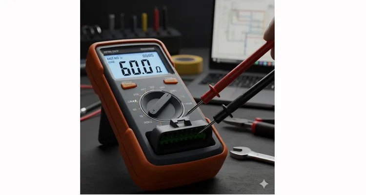
| ~60Ω | Static Check Passed | Do not stop here. Proceed to live voltage checks and dynamic testing. |
| ~120Ω | Missing One Terminator | Find out why one is missing (unplugged module? wrong part?) before adding anything. |
| OL (Open) | Open Circuit | Check for breaks in both CAN wires or complete absence of terminators. |
Now, let’s understand why these numbers tell that story, and how to move from clue to conviction.
You’re staring at a cryptic DTC U0100 – Lost Communication. The dashboard is lit up. A critical machine is dead. Everyone points to the CAN network. You grab a multimeter, check the CAN lines, and see 60 ohms, 120, or maybe 0. The shop has rules for these numbers, but rules fail, leading to wrong parts replaced and hours wasted.
This isn’t about memorizing numbers. It’s about decoding the electrical conversation on two wires. We go past “60Ω is good” to why it’s good, when it lies to you, and how to be sure. If you fix Tier 1 automotive robots, forestry harvesters, or marine controls, this is your systematic approach.
The Scene: Decoding Intermittent Silence in Your CAN Network
The failure is rarely obvious. It’s a ghost. Intermittency is the clue, tied to system state.
- Does it fail only when hydraulics engage, causing a ground shift?
- Does communication drop when a high-current relay clicks on?
- Does your aftermarket GPS tracker lose data when the factory telematics module broadcasts? That’s bus overload.
The telltale sign is multiple unrelated systems failing. Transmission acts up and the trailer ABS lights up. Why? They share the CAN bus highway. Block it, and everyone goes quiet. For a deeper dive into tracking down these elusive faults, our guide to diagnosing intermittent CAN bus failures provides advanced strategies.
Your first tool isn’t the scanner. It’s the multimeter. The scanner says what failed. The multimeter, used right, says why.
The Electrical Foundation: Terminators Explained (Beyond the Textbook)
Most guides stop at “a CAN bus needs two 120-ohm resistors.” True, but incomplete.
The goal isn’t just to stop signal reflections. It’s to tune the network’s characteristic impedance—like tuning a guitar string for a clean note, not a muddy ring or a choked sound. The 120-ohm target, defined in the ISO 11898 standard for high-speed CAN, ensures a digital ‘pluck’ from a transceiver arrives as a crisp square wave, with no signal ringing that mimics extra data bits.
The Key Insight: These two 120-ohm resistors are installed in parallel across the bus (between CAN_H and CAN_L) at two separate modules. When you measure resistance across the bus with the vehicle power off and modules disconnected, you’re measuring the parallel combination of all resistive loads.
The Critical Miss: You must isolate the network for this reading. You’re testing the passive infrastructure, not the active electronics inside modules.
From Meter Reading to Diagnosis: Your Decision Tree
Your multimeter shows a number. Now, think—don’t just match a chart.
The Diagnosis Logic for CAN Bus Resistance
- 0-10Ω (Short): CAN_H and CAN_L are touching. This is a physical hunt for pinched wires or water intrusion.
- ~40Ω (Three Terminators): An extra 120Ω load is present. Suspect an aftermarket device or OBD-II dongle with built-in termination.
- ~60Ω (Correct): The electrical stage is set. But this doesn’t prove the modules (“actors”) are functional. It only confirms the termination resistors are likely correct.
- ~120Ω (One Missing): Only one terminating resistor is working. It might function in a short network, but will be unstable over long cable runs.
- Open Circuit (OL): The circuit is broken. Wires are cut, or no terminators are connected.
The Core Diagnostic Move: The Split-Half Method
Don’t just probe the OBD-II port. To localize a fault, you must split the network. This Split-Half Method is your most powerful tool.
Step-by-Step: The Split-Half Measurement Procedure
- Power OFF everything. Disconnect the battery.
- Find the DLC (OBD-II port), but don’t test there. It’s a tap, not a break point.
- Unplug a central module (e.g., ECM, gateway). This electrically splits the network into two legs.
- Set multimeter to Ohms (Ω). Probe between Pin 6 (CAN_H) and Pin 14 (CAN_L) at the DLC.
- Read, then interpret. With the module unplugged, one leg should read ~120Ω (has a terminator), the other OL (no terminator). Reconnected, it should be ~60Ω.
The Split-Half Method identifies which leg of the network holds the fault, cutting diagnosis time dramatically.
Step-by-Step Diagnosis: From Reading to Root Cause
Apply the logic with real scenarios.
Scenario 1: You Read 0Ω (Short)
- The Hunt: Confirm with power OFF. Use the Split-Half Method to isolate the short to Leg A or B. On that leg, unplug devices one by one, watching the multimeter for the short to disappear.
- Common Culprits: Pinched harness near moving parts (seat rails), or corroded connectors from water intrusion.
Scenario 2: You Read 120Ω (One Missing Terminator)
- The Hunt: Use the Split-Half test. One leg reads ~120Ω (good), the other OL (problem).
- Critical Step: Don’t just add a resistor. Find why it’s missing. Was a module replaced incorrectly? Is the designated terminating module unplugged? Check the wiring diagram.
Scenario 3: You Read 40Ω (Three Terminators)
- The Hunt: Often the simplest. Remove any aftermarket devices (trackers, dongles) plugged into the OBD-II port or spliced in. The reading should snap back to 60Ω. Understanding why these devices fail is key; see our analysis of common OBD2 splitter cable problems and fixes.
Scenario 4: You Read an Open Circuit (OL)
- The Hunt: Perform a continuity check on CAN_H and CAN_L wires. Ensure modules containing the termination resistors are powered and connected.
The 5 Most Common CAN Bus Diagnosis Mistakes
- Measuring with power on. This reads the internal electronics of all modules (2-5kΩ), not the network terminators. Always power down first.
- Not splitting the network. Testing the whole bus only confirms a problem. The Split-Half Method finds its location.
- Assuming 60Ω means perfect health. A high-resistance short or failing transceiver can still show ~60Ω when powered down, but fail when live.
- Skipping the voltage check. After resistance, power up (key on, engine off). Measure DC voltage: CAN_H to ground (~2.5V) and CAN_L to ground (~2.5V). A major deviation points to a transceiver issue.
- Ignoring the physical harness. CAN faults are often physical. Visually inspect for abrasion, pinch points, green corrosion, and damaged cable shields. In harsh environments like agriculture, these failures are systematic; our J1939 cable agriculture survival guide details the battle against vibration and chemistry.
How to Know You’re Really Done: The Validation Test
Fixing the resistance is just step one. Validate with a dynamic test.
- Clear all DTCs.
- Monitor CAN bus activity. Confirm all modules report “Active.”
- Create a system load. Activate high beams, max HVAC, heated seats—any high-draw circuit. Cycle power windows/locks. Stability under load is key.
- Perform an operational test. Drive the vehicle or run the machine. Vibration, thermal cycles, and electrical load together are the ultimate test.
When the Problem Isn’t the Wiring: The Interface Integrity Gap
Sometimes, resistance and voltage are perfect, but glitches remain. The culprit can be signal integrity at the interface—where a diagnostic tool or added module connects.
A low-quality cable or adapter can inject noise, add capacitance, or create impedance mismatches, destabilizing the network. This is why understanding CAN bus EMI shielding fundamentals is crucial for robust designs.
What to Look for in a Quality CAN Interface Cable:
- No Internal Termination: It must NOT add a 120Ω resistor unless it’s a designed network endpoint.
- Signal Isolation: Optical or galvanic isolation is non-negotiable to block ground offsets and voltage surges.
- Shielded, Twisted-Pair: The cable must maintain 120-ohm impedance. The shield should be drained at one end to prevent ground loops.
- Precision-Molded Connectors: Intermittent faults live here. Gold-plated pins and firm strain relief are essential. The debate between crimp vs. solder for vibration reliability is settled on our production floor.
In system integration, the cable is the foundation of data integrity. A $20 connector can compromise a $20,000 system. We engineer them as the primary interface component because your real cost is in debugging time, not the cable itself. The true cost analysis of choosing a supplier is explored in our article on the true cost of a custom cable.
At our facility, we engineer the interface. Every CAN bus cable gets a 4-point check: continuity, short-circuit, impedance verification, and hi-pot isolation testing. This rigor stems from our IATF 16949 PPAP zero-defect cable process, a core part of our IATF 16949:2016 certification. We’ve seen cheap cables stall expensive machines. Our engineering team provides direct support for OEM customizations and integration troubleshooting for industrial, marine, and automation applications.
FAQ: Myths, Mistakes, and Real Answers on CAN Bus Health
Q: I measure 60Ω exactly. Is the CAN bus ruled out?
A: For the passive wiring, likely yes. But you must do powered voltage checks and dynamic tests. A failing transceiver can pass a static resistance test.
Q: Why does my CAN bus measure 60 ohm but still not work?
A: 60Ω only confirms terminators. It doesn’t verify module power, healthy transceivers, or the absence of electrical noise on the line.
Q: My reading drifts between 50-70Ω. Is this a problem?
A: Minor variation is fine (meter tolerance). If it drifts steadily or jumps when you wiggle the harness, you have a poor connection.
Q: Can I just add a resistor to fix a 120Ω reading?
A: Find the root cause first. Adding a resistor in the wrong place (e.g., mid-bus) creates impedance mismatches and is worse than the original problem.
Q: What does a ~2-5kΩ reading mean?
A: You measured with power on or modules connected. You’re reading the parallel resistance of all module electronics. Power down for a valid test.
Q: How do I find which module has the termination?
A: Consult the service documentation. Typically, it’s the ECM at one end and the Instrument Cluster or Body Control Module at the other.
Q: What about CAN FD networks?
A: The basic DC resistance and voltage diagnosis are the same. CAN FD is even more sensitive to improper termination and cable quality.
Q: When should I use an oscilloscope vs. a multimeter?
A: Use a multimeter to find the fault (short, open, wrong resistance). Use an oscilloscope to analyze the signal quality (ringing, noise, waveform shape).
Stuck on a network gremlin? When basic fixes fail, you need engineered solutions, not generic parts. If you’re integrating systems or face harsh environments, the right interface is critical.
Let’s discuss the electrical specifics of your application.
- Message me on WhatsApp: I’m Linda. Our engineering team can review your pinout and needs. Click here to chat.
- Send your schematic: For OEM and customization support, use our Contact Page. Send diagrams for review.
We are an IATF 16949 certified facility, also compliant with ISO 14001 environmental standards. Our 5S management and 4-step quality inspection process is built for reliability. Tell us what you’re building.
