

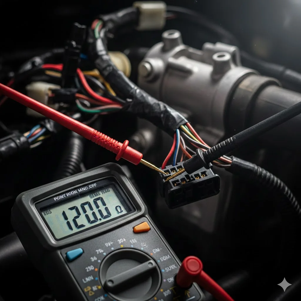
You know the drill. Communication drops. The dash lights up with a symphony of U-codes, then goes quiet. You grab your multimeter and probe the OBD-II port—Pin 6 to Pin 14. It reads 120Ω. “That seems fine,” you think. It’s a 120-ohm bus, right? Then it clicks: that’s the value of one resistor, not the network. Your CAN bus is running with half its required termination, a setup guaranteed to create problems where none should exist.
This isn’t speculation. That 120Ω reading with the system powered down is a concrete diagnostic outcome. It tells you, without doubt, that your vehicle’s communication backbone has lost an endpoint. Let’s trace this fault back to its origin, using the same forensic approach we apply to 500,000+ harness assemblies in our factory quality control process.
Why 120Ω Doesn’t Mean “Half Working”—It Means Critically Compromised
Forget textbook definitions. Picture your CAN bus as a taut guitar string. Pluck it, and it rings clear. The 120Ω termination resistor at each end is what absorbs the vibration, stopping the signal energy from bouncing back and creating a distorted mess of echoes. When your meter shows 120Ω at the OBD port, you’re not confirming a healthy bus. You’re confirming that one end of that “string” is loose, and every digital pulse is echoing into garbled noise.
The parallel resistor math is simple, but in the real world, a 120Ω failure mode is rarely about a single bad component. It’s a symptom of a deeper system failure. Based on our factory forensic analysis of returned units, we’ve identified distinct failure patterns most generic guides overlook entirely.
The Four Hidden Failure Modes That Manifest as 120Ω
- The Thermal Fracture (Not Just “Heat-Related”)
Symptoms emerge after 15-20 minutes of operation. Software is often wrongly blamed. The reality we’ve proven: internal termination resistors inside ECUs can develop micro-fractures at their solder joints. As the module heats up, thermal expansion widens these hairline cracks. The resistance soars to a near-open circuit (>1MΩ), effectively vanishing from the network. Let the module cool, and the crack might contract, temporarily “healing” the connection. The 120Ω reading is often only present when the suspect module reaches its operating temperature. - The Architecture Incompatibility
You swap in a “good” used BCM or ECM. Suddenly, the network is dead. A termination check reveals 120Ω. The issue isn’t a faulty module, but a mismatch in network topology. The donor vehicle may have had termination in the gateway module, while your vehicle’s architecture expects it in the BCM. You didn’t break it; you installed a component from a different logical design. - The Manufacturing Defect That Passes Bench Tests
Your prototype or aftermarket interface works flawlessly on your development bench, where your test fixture provides perfect termination. In the vehicle, it fails. The 120Ω reading confirms the vehicle supplies only one termination point, and your bench setup was masking this deficit. This exposes the risky assumption that all ECUs or interfaces in a catalog include internal termination, when many OEMs deliberately assign this role to specific, designated modules. - The Vibration-Induced Intermittent
Predominant in heavy equipment, construction, and off-road vehicles. A termination resistor pack might look securely connected, but its crimp connection has fatigued under specific vibration frequencies. The resistance fluctuates wildly between 120Ω and open circuit. We’ve diagnosed faults that only manifested at certain engine RPMs or when traveling over washboard terrain, directly correlating mechanical stress with electrical failure, a topic we explore in depth in our guide on diagnosing vibration-induced cable failures.
Factory Diagnostic Protocol: Isolating Termination Faults in 15 Minutes
Move beyond basic “disconnect and check” lists. This is the structured diagnostic matrix our technicians use on the production line and for analyzing field returns. For a comprehensive walkthrough of foundational checks, see our CAN bus health check guide.
Phase 1: Establish the Electrical Crime Scene
- Power everything down completely. “Ignition off” is insufficient. Some modules stay awake for minutes. Wait a full 5 minutes to ensure all transceivers are asleep.
- Measure at the OBD port (Pins 6 & 14). Note the exact value. A stable 118-122Ω confirms the single-terminator hypothesis. A reading of 115Ω or 125Ω points to a different issue.
- Critical Step Most Miss: Measure resistance from Pin 6 to chassis ground, then Pin 14 to ground. Any reading comfortably below 1MΩ suggests leakage or a short to ground/power, which can completely mask or distort termination fault readings.
Phase 2: The Topography Autopsy (Not Just Topology)
Don’t just disconnect modules at random. Methodically create a resistance map of the network:
- At the OBD port (your central junction).
- At each suspected endpoint connector (with the module physically disconnected).
- Directly across any accessible termination resistor itself (if in a standalone pack).
The Disconnection Test with Enhanced Interpretation:
| Meter Reading After Disconnect | What It Means | Next Action |
| Jumps to OL (>1MΩ) | You removed the only good terminator. The open fault resides at the opposite network end. | Investigate the other endpoint module, its connector, and harness. |
| Stays at ~120Ω | The disconnected module contained the faulty termination path. Its internal resistor is open or missing. | Focus repair or replacement efforts on this specific module or its connector. |
| Drops to ~40-50Ω | You likely have three resistors on the bus, a clear sign of incorrect aftermarket modifications. | Locate and remove the unauthorized third termination resistor. |
| Drops to ~60Ω | Crucial finding. This means you’ve isolated a short circuit, not an open termination. Your original 120Ω was the parallel result of one good resistor and a partial short. | Start diagnosing a short between CAN_H and CAN_L. |
Phase 3: Environmental Interrogation
- Does the resistance reading change when you physically flex the harness near key connectors or splices?
- Does the reading stabilize when you cool a specific module with a quick blast of compressed air?
- Does gently tapping the ECU or resistor pack with a plastic tool cause the meter to jump? This technique is part of a broader strategy for diagnosing intermittent CAN bus failures.
The Repair Mistake That Makes Problems Worse (Adding Third Resistors)
This is a weekly occurrence in our support chats. A technician finds 120Ω, so they add another 120Ω resistor at the OBD port. The result is three parallel resistors (120Ω || 120Ω || 120Ω = 40Ω). This overloads the CAN transceivers, increases quiescent current draw, and creates not one, but multiple signal reflection points. The network might limp along but will never be reliable.
Correct Repair Strategy by Fault Location:
- Integrated Resistor Failure: Typically requires module replacement. Adding an external 120Ω resistor across the connector pins is a field fix, not a factory repair. If you do this, the resistor must be placed within 5cm of the connector to avoid creating a “stub” that causes impedance mismatches at high data rates.
- Discrete Pack Failure: Replace with a high-quality 1% tolerance metal film resistor. Avoid carbon film resistors; their value drifts significantly with temperature. We source military-grade components rated for -40°C to 150°C for our assemblies, adhering to standards like ISO 16750 for vibration reliability.
- Harness-Level Resistor: Often damaged by heat or stress during prior repairs. Replace it and ensure proper strain relief. We’ve forensically examined failures where unsupported resistor leads snapped due to vibration. The debate between connection methods is critical; learn more in our crimp vs. solder for vibration reliability guide.
When 120Ω is Actually Normal: CAN FD & Network Exceptions
Not every 120Ω reading spells doom. Context is critical.
- CAN FD Networks: These often employ switchable or active termination circuits that change impedance between arbitration and data phases. A 120Ω reading in a specific mode can be perfectly normal.
- Partial Networking / Sleep Systems: Some ECUs have internal termination that is only enabled when the module is fully awake, activated by a specific wake-up signal.
- Measurement Timing Error: If modules haven’t fully entered sleep mode, their transceiver bias networks can present a combined resistance of around 120Ω across the bus, even with two perfect terminators present. This is why the mandatory 5-minute wait is non-negotiable for accurate diagnosis.
Critical Distinction: Low-speed CAN (LS-CAN) and single-wire networks (like GMLAN) use entirely different termination schemes, often involving resistor-capacitor networks. Applying high-speed CAN diagnostic logic to these buses will lead you astray. Understanding these legacy systems is crucial; our guide to legacy OBD2 protocols can help. For the official technical definition of the relevant physical layer standard, refer to ISO 11898-2 (Road vehicles — Controller area network (CAN) — Part 2: High-speed medium access unit).
From Diagnosis to Prevention: Building Termination-Fault-Proof Systems
Our 4-step quality inspection catches what others miss because we look for the cause, not just the symptom. Our processes are backed by certifications like IATF 16949 and ISO 14001. Here’s what we enforce that many don’t:
- The ≤5cm Resistor Placement Rule
Many factories drop a termination resistor wherever it’s convenient in the harness. We mandate it must be within 5cm of the actual connector pin. Why? Even 15cm of wire between the resistor and the true bus end acts as a “stub,” creating impedance mismatches that cause reflections at speeds of 1Mbps and above. Last quarter, this rule led us to reject a batch of 2,000 OBD cables for a tier-1 supplier—their design would have caused cold-start-only intermittent faults in the field. - Thermal Stress Testing Beyond Room Temp
Standard QC often checks resistance at 25°C. We subject assemblies to thermal cycling from -40°C to 125°C while monitoring resistance in real-time. This is how we pinpointed a specific batch of off-brand resistors that failed in 85% of field returns for a 2022 model year agricultural controller—they only went high-resistance when hot. This is especially relevant for harsh environments covered in our J1939 cable agriculture survival guide. - Crimp Integrity Verification (Beyond Continuity)
A resistor can measure a perfect 120Ω on a benchtop tester yet fail in a month due to vibration. Why? The crimp wasn’t radially compressed evenly, leading to fatigue. Our cross-section analysis of failed field returns consistently shows this. For high-vibration applications, we now specify and verify ultrasonic welding for termination connections, a method proven in applications from forestry equipment to reefer units.
Advanced Q&A: Termination Problems Other Guides Don’t Cover
Q: We measure 120Ω only during engine cranking, then it goes back to 60Ω. Is this okay?
A: No. This typically indicates a module with aging or failing buffer capacitors on its 5V reference or power supply. During the voltage sag of cranking, the CAN transceiver browns out and disables, temporarily removing its termination from the network. Check the power supply conditioning circuits on the affected module.
Q: Our farm tractor shows a perfect 60Ω but still gets arbitration errors at 500kbps. Can termination still be the culprit?
A: Possibly. It’s about impedance matching at frequency, not just DC resistance. A resistor placed even 20-30cm down a wire “stub” from the actual connector appears as 120Ω to your meter but creates a terrible impedance mismatch at high frequency. We’ve traced this to “hidden stubs” in some OEM harnesses. Diagnose this with a TDR (Time Domain Reflectometer) or consider the durability needs outlined in our J1939 cable engineering guide.
Q: Why does my luxury car show 114-118Ω for a single termination, not 120Ω?
A: Parasitic resistance. Every connector pin (1-3mΩ), every meter of wire (20-30mΩ), and the protection circuits within each sleeping transceiver add tiny amounts of resistance in parallel. In a complex network with 30+ modules, you’re measuring one 120Ω resistor in parallel with several hundred milliohms of accumulated parasitic resistance.
Q: What’s the story with a ~90Ω reading?
A: This strongly suggests three 120Ω resistors exist on the bus (which would parallel to 40Ω), but one has a high-resistance connection—perhaps 200-300Ω due to corrosion or a failing joint—pulling the total measured value up toward 120Ω. You’re hunting for a corroded connector or a resistor beginning to fail, not a missing one.
Q: Can PWM noise from fans or actuators mess with my resistance check?
A: Absolutely, if the system is powered. PWM-driven actuators induce current fluctuations on the power and ground lines, which can couple into the CAN bus and cause your multimeter reading to dance between 100-150Ω. Always perform the critical termination resistance check with the system completely powered down. For managing electrical noise, see our field guide to CAN bus EMI shielding.
Q: Should our custom data logger have switchable termination?
A: For any diagnostic tool or development interface, yes—it’s a best practice. Switchable termination prevents your device from accidentally being the third terminator on a network. Our design rule: if the device could be plugged in at either a network end or in the middle, make the termination software/configurable. This is a key consideration in custom cable design. The principle of transmission line termination is well-documented, including resources like the Texas Instruments application note on CAN bus layout.
Case Study: Mining Excavator Intermittent Failure
Problem: A 40-ton excavator suffered random communication drops and inconsistent 120Ω readings. Standard diagnostics implicated the main controller.
Our Investigation: We performed a vibration analysis correlated with engine RPM. The resistance fault (jumping from 120Ω to OL) occurred precisely when the machine turned and the engine hit a specific resonant frequency.
Finding: The vibration had caused a micro-fracture in the solder joint of a termination resistor hidden inside a supposedly sealed connector. The crack was invisible to the naked eye, only clear under 20x magnification.
Solution: We redesigned the harness section using strain-relieved, potted resistor packs mounted on vibration isolation dampeners. Result: The client eliminated over 12 hours of unscheduled downtime per month. This application of cold welding for vibration resistance is detailed further here.
A reliable network is built on sound physics, not just correct protocols. If you’re battling elusive CAN faults or engineering a system that cannot tolerate intermittent communication, the integrity of every termination point is non-negotiable. Sometimes the issue extends beyond termination to the port itself; if you face complete silence, our OBD2 port no-communication guide may help.
We provide the engineering-level analysis needed to solve these issues permanently. Share your specific failure symptoms, network topology, and operating environment via our Contact Page for a structured technical review. For an immediate discussion on waveform analysis or component-level specifications, message our lead engineer directly on WhatsApp.
Contact Page: https://obd-cable.com/contact/
