

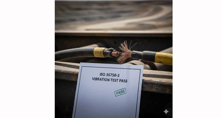
If you’re overseeing electrical systems for off-road equipment, ISO 16750-3 is a familiar benchmark. It’s the established vibration standard for validating automotive electrical components. However, from our vantage point on the factory floor and failure analysis lab, we observe a recurring, costly contradiction: a perfect lab certificate for ISO 16750-3 filed away, while a physically destroyed harness from the field sits in a warranty return box.
The standard itself isn’t the problem—it’s a necessary baseline. The profound error lies in treating this baseline as the ultimate qualification milestone.
This analysis delves into the operational chasm between standard compliance and real-world survival. We will detail the specific failure mechanisms that generic lab tests overlook, explain the application-specific methodology we employ to reveal them, and provide you with a concrete framework to vet your supplier’s true engineering depth. This is the transition from hoping a cable passes a test to knowing your wiring system will endure in service.
The Laboratory Mirage: Where Standard Vibration Testing Diverges from Field Reality
ISO 16750-3 prescribes defined vibration profiles—specific frequencies, acceleration levels (G-forces), and durations—to simulate a generalized vehicular environment. The assessment is conducted on an isolated cable sample, mounted in a controlled, repeatable manner on an electrodynamic shaker table within a pristine laboratory setting.
This controlled environment is where the fundamental disconnect originates. In your actual machinery, the cable assembly does not exist in a sterile fixture. It is routed through sharp, stamped-metal grommets, clamped directly to a resonating chassis rail, and bent tightly into a connector at a dynamic swivel joint. It endures not just isolated vibration, but a simultaneous cocktail of mechanical and environmental stresses.
Consider the lifecycle of a cable on a hydraulic excavator’s boom. The ISO test might subject it to a simplified back-and-forth motion. On the actual machine, that identical cable concurrently faces:
- Micro-abrasion: Continuous, low-amplitude sawing against a welded structural seam with each boom articulation.
- Torsional Loading: Cyclical twisting at the entry point to a rotating union or pivot joint.
- Pinch-Point Stress: Localized, high-pressure compression from a clamp that is overtightened or shifts during operation.
- Thermal Cycling: Extreme temperature fluctuations, from sub-zero ambient conditions to intense radiant heat near the engine or hydraulic systems, which drastically alter polymer flexibility and metal fatigue limits.
The standard test validates a cable’s inherent resistance to a prescribed vibrational input. It does not—and by design, cannot—validate the installed durability of an integrated wiring system. This gap between component test and system performance is the origin of the most expensive and recurrent field failures.
The Real Culprits: Failure Mechanisms Omitted by Standardized Testing
A broken wire is the visible symptom. The engineer’s critical task is to diagnose the root-cause mechanism. Through systematic forensic analysis of field-returned failures, we consistently isolate four primary mechanisms that conventional ISO 16750-3 testing fails to adequately replicate.
- Fretting Fatigue at Constrained Interfaces. This is often the most pervasive, silent failure mode. Where a cable is firmly clamped or passes through a fixed guide, its ability to move freely with ambient vibration is restricted. This constraint induces microscopic, reciprocal sliding (on the scale of microns) between the clamp surface and the cable jacket. Over millions of cycles, this action initiates fretting wear, a process that progressively erodes the outer jacket, degrades the underlying insulation, and ultimately severs the individual copper strands. Critically, standard test fixtures frequently employ soft, non-abrasive mounts that completely prevent this specific wear mode, resulting in a misleading pass. (For a deep dive into systematic failure diagnosis, see our guide on forensic analysis of vibration-induced wire fatigue.)
- Resonance in Unsupported Cable Spans. A length of cable secured between two anchor points behaves like a tensioned string, possessing a natural resonant frequency. If the dominant vibration spectrum of the machinery excites this frequency, the cable can enter a state of resonance, oscillating with an amplitude significantly greater than the base input from the machine frame. This amplified whipping motion concentrates extreme cyclical stress at the termination points (the connector crimps or solder joints), precipitating rapid metal fatigue and failure. Standard test setups, by rigidly securing the entire sample, artificially dampen these resonant effects and mask the inherent risk.
- Work-Hardening of Fine Copper Strands. The high-frequency, low-amplitude vibration endemic to diesel engines and certain hydraulic circuits does not produce large bending radii. Instead, it induces repeated, minuscule flexing within the fine strands of a conductor. This process, known as work-hardening or cold-working, increases the hardness and tensile strength of the copper but drastically reduces its ductility. Over time, the strands become brittle and can fracture under what would otherwise be a routine bending load during service or maintenance. This is a fundamental material fatigue limit issue not typically explored by standard broadband frequency sweeps.
- Synergistic Degradation from Combined Stresses. In actual operation, mechanical vibration is never an isolated stressor. It is invariably accompanied by thermal extremes, moisture, hydraulic fluid, and particulate contamination. The interaction is synergistic: operational heat softens thermoplastic jackets (like PVC), making them exponentially more vulnerable to abrasion. Conversely, cold temperatures embrittle materials like polyurethane (PUR), causing micro-cracks initiated at stress points to propagate rapidly. Testing vibration and temperature in a sequential manner (vibration then temperature cycling) entirely misses this accelerating, coupled degradation effect that occurs when stresses are applied concurrently.
This mechanistic understanding mandates a paradigm shift in validation philosophy: the test subject must evolve from a simple cable component to the complete wiring system—incorporating its real-world routing, clamping strategy, and connector interfaces—and it must be evaluated under simultaneous combined environmental stresses.
Our Protocol: Engineering an Application-Specific Real-World Validation
Our validation methodology is deliberately application-centric; it does not commence in the test lab. It begins with a deep dive into your specific operational envelope. We either request, or preferably collaborate to gather, the actual environmental data: data-logger recordings capturing the vibration spectra (including shock, random, and sine components) from critical mounting locations, operational temperature ranges and cycles, and exposure to potential contaminants.
Synthesizing this data, we engineer a bespoke Real-World Validation Protocol. This is a targeted engineering exercise, not a generic compliance check.
Step 1: Fabricate the Test Article – A Functional Replica, Not a Laboratory Sample. We do not test a straight piece of cable. We manufacture a complete harness assembly that precisely replicates your documented routing. We use the specified or identical clamps, grommets, connector series, and enforce the exact bend radii from your drawings. Known high-stress zones are deliberately incorporated.
Step 2: Apply Synchronized Multi-Axis Stress. This representative harness is mounted within a combined environmental chamber equipped with a multi-axis vibration system. Here, temperature cycling and vibration input are applied simultaneously. The vibration profile is not an off-the-shelf curve from a standard; it is an accelerated life test profile, derived from your field data and tailored to efficiently excite the specific failure mechanisms identified as risks.
Step 3: Implement Real-Time Failure Detection. We do not simply run the test for a prescribed duration and conduct a pass/fail inspection at the end. We employ Continuous Resistance Monitoring (CRM) on every conductor. This complements other advanced diagnostic techniques like Time Domain Reflectometry (TDR), which we use for pinpointing intermittent electrical faults in complex networks. The instant a single wire strand fractures, causing a measurable resistance spike, the system catalogs the exact time-to-failure and the concurrent environmental conditions (temperature, vibration phase). This provides not just a binary result, but crucial data on failure mode and precise time-to-failure under the applied stress regime.
Step 4: Conduct Post-Test Forensic Analysis. Every test sample that reaches a failure endpoint undergoes detailed forensic dissection. We examine fracture points under magnification to definitively identify the failure mechanism—confirming fretting, bending fatigue, or brittle fracture—and directly correlate it back to the test conditions and physical design of the harness.
Step 5: Iterate Design and Validate the Solution. The objective of this rigorous process is not to document failure, but to engineer robustness. We work alongside your design team to propose and implement targeted countermeasures—a specialized jacket material, an anti-abrasion sleeve, a redesigned overmolded strain relief—and then repeat the validation protocol to quantitatively demonstrate the improvement. This is predictive engineering, not retrospective inspection.
Quantifiable Proof: Extending Service Life from 1,400 to Over 11,000 Hours
We executed a definitive A/B comparison for a client in the mining sector. The challenge: a CAN Bus cable on a 240-ton haul truck, subjected to severe chassis vibration and wide temperature excursions.
- Test A (Standard-Compliant Baseline): A commercially available, high-quality PUR-jacketed cable was tested to ISO 16750-3 (Profile M, 2.5Grms, -40°C to +125°C, sequential tests). It successfully passed the required duration. The same cable, when integrated into a realistic harness and subjected to our Real-World Validation Protocol (simultaneous temperature/vibration with representative abrasive clamp interfaces), exhibited its first conductor fracture at approximately 1,400 hours.
- Test B (Application-Engineered Solution): Using the identical base cable, we implemented three design modifications informed by failure mechanism analysis:
- Integration of an abrasion-resistant textile sleeve over the jacket at all clamping locations.
- Specification of a gel-filled, mechanically clamped connector backshell to eliminate all strand movement at the wire-to-terminal interface.
- Application of a dual-durometer overmold at a critical 90-degree bend to distribute flexural stress.
This modified system was tested exclusively under our harsher, combined-stress Real-World Validation Protocol.
The Result: The first failure in the engineered system occurred at over 11,000 hours—representing a nearly 8-fold increase in functional service life under identical accelerated aging conditions.
The 1,400 hours vs. 11,000 hours data point is not merely a laboratory statistic. It directly quantifies the impact on Total Cost of Ownership (TCO): a drastic reduction in unplanned downtime, significantly lower warranty and repair costs, and substantially improved machine availability. This is the tangible engineering value that transcends a basic compliance certificate. This demonstrates why the true cost of reliability must consider total lifecycle value, not just initial purchase price. This is the core design philosophy behind our J1939 ArmorLink™ Cable Assembly – Engineered for 11,000+ Hour Vibration Life, where this proven methodology is translated into a production-ready product.
Five Critical Misconceptions in Cable Specification & Validation
Misconception 1: “We are purchasing a cable component.”
Reality: You are procuring a wiring system that must function as an integrated assembly. A cable with perfect electrical specs will fail rapidly if its jacket abrades against a chassis edge.
Actionable Step: Transform your RFQ into a system drawing. Specify the exact clamp part numbers (or material/finish), grommet inner diameter and material, and minimum dynamic bend radius for each harness segment. You are sourcing guaranteed performance, not just conductive material.
Misconception 2: “Testing vibration and temperature sequentially is adequate.”
Reality: Sequential testing ignores the synergistic acceleration of degradation. A jacket softened by heat abrades orders of magnitude faster under concurrent vibration.
Actionable Step: For any mission-critical or high-reliability application, mandate combined environmental stress testing where vibration and thermal cycling are applied concurrently.
Misconception 3: “This engineering prototype is valid for production qualification.”
Reality: A lab sample assembled with hand-soldered connections and bespoke strain relief behaves fundamentally differently than a unit produced with automated crimping, robotic molding, and standard work instructions.
Actionable Step: Insist that all validation testing be performed on samples built using production-intent tooling, processes, and documented workmanship standards.
Misconception 4: “Without field data, we must default to the standard profile.”
Reality: Modern machinery is instrumented. Relying on a generic profile is an unquantified risk.
Actionable Step: Deploy a basic tri-axial accelerometer data logger on a prototype or similar machine. Even a short-duration recording from the actual mounting location provides a more accurate foundation for test design than any generic standard.
Misconception 5: “A ‘Pass’ result indicates sufficient reliability.”
Reality: A binary pass/fail reveals nothing about the design margin (how close to failure you are) or the failure mode (how it will eventually fail).
Actionable Step: Demand quantitative data from your supplier: “What was the demonstrated time-to-failure in your accelerated life test?” and “What is the calculated Mean Time Between Failures (MTBF) for my target service life?”
The Five-Question Supplier Technical Audit
Disregard the generic supplier qualification checklist. In your next technical review with a potential supplier, pose these five questions. The depth and clarity of their responses will instantly differentiate a commodity vendor from a genuine engineering partner.
- “Can you provide a test report demonstrating combined vibration and temperature testing on a complete harness assembly that replicates a real installation geometry, not just a simple cable-on-a-board sample?”
- “Describe your process for translating field-recorded vibration data into an accelerated test profile. Which specific engineering models (e.g., Miner’s rule for cumulative fatigue, the inverse power law) do you apply to correlate test time to field life?”
- “Do you employ Continuous Resistance Monitoring (CRM) or similar real-time diagnostics during vibration tests to capture intermittent faults and pinpoint the exact moment of failure, as opposed to only performing a continuity check at test conclusion?”
- “Can you share an anonymized failure analysis report from a previous project that details the root-cause mechanism of a vibration-induced failure and precisely documents the design modification that resolved it?”
- “How do your in-process quality gates (e.g., your 4-step inspection) actively control vibration-critical attributes such as crimp compression force, conductor strand alignment within the crimp barrel, and final clamp installation torque?”
Translating Failure Analysis into Robust Design
When our validation testing identifies a weakness, we do not propose a vague “upgrade.” We develop and validate a solution engineered to defeat the specific failure mechanism.
Countering Fretting Fatigue Through Material Engineering
Where fretting wear is identified as the dominant failure mode, simply specifying a harder jacket can be counterproductive, potentially increasing friction. Our approach involves collaborating with polymer compounders to develop jacket materials with engineered fillers or embedded solid lubricants. These additives create a sacrificial layer at the wear interface, dramatically reducing the coefficient of friction and protecting the primary jacket and underlying conductors.
Mitigating Resonance with Integrated Mechanical Design
Rather than merely increasing the quantity of mounting clips—which can introduce new stress points—we design and mold custom overmolded components. These serve a dual purpose: providing graded strain relief to manage bend stress and acting as tuned damping masses to alter the harness assembly’s natural resonant frequency, moving it away from dominant environmental excitation frequencies.
Eliminating Termination Failures via Advanced Interfacing
To prevent work-hardening and fatigue failures at the critical wire-to-connector junction, we advance beyond standard crimping. Solutions include potted connectors or gel-sealed backshells that completely encapsulate and immobilize the wire transition zone. This converts an area of flexible, individual strand movement into a single, solidly supported mechanical unit, eliminating relative motion. For a detailed comparison of termination methods, see our guide on crimp vs. solder for vibration reliability.
Ensuring Consistency Through Controlled Manufacturing
Reliability is designed on the drawing board but is ultimately realized on the production floor. Our 5S-managed and climate-controlled manufacturing environment is structured to minimize variability. Parameters such as crimp depth/force, molding temperature/pressure, and final assembly torque are rigorously controlled and monitored. In high-vibration applications, process variability is the antithesis of predictable performance. This discipline is formalized within our certified IATF 16949 PPAP process, a cornerstone of our IATF 16949 Certified J1939 Cable – Full PPAP Documentation Available product line.
Our foundational ISO 9001, IATF 16949, and ISO 14001 certifications establish the essential quality management system. The over twenty years of direct factory experience diagnosing and resolving field failures provides the crucial engineering judgment that animates this system.
Frequently Asked Questions on Real-World Vibration Validation
Q1: Does this mean ISO 16750-3 is obsolete?
A: Not at all. ISO 16750-3 remains an indispensable baseline screening tool. It efficiently identifies components that are fundamentally unsuitable for any automotive-type vibration environment. The error lies in misconstruing this baseline screening as a comprehensive validation for long-term reliability in your specific, often more severe, application.
Q2: What is the cost premium for this level of validation?
A: There is an upfront investment in engineering analysis and specialized test time. However, this cost is almost invariably insignificant when weighed against the fully-loaded cost of a single in-field failure. This includes not just the part replacement, but also emergency logistics to remote sites, skilled technician labor, and—most critically—the prodigious cost of machine downtime. We position this validation as a fixed-price reliability insurance policy.
Q3: Can you benchmark our current cable assembly?
A: Absolutely. A benchmarking assessment is a common and valuable engagement. We subject your existing cable or harness to our Real-World Validation Protocol. This yields a performance baseline, clearly identifies the weakest links in the system, and generates objective data to support any necessary design rationale.
Q4: Our project is in the early design phase with no field data available.
A: We can proceed effectively. Based on the machine classification (e.g., 400-ton mining haul truck, agricultural combine), powertrain type, and intended mounting zone, we leverage a proprietary library of historical environmental data from analogous applications. This allows us to propose a conservative, application-tailored test profile to guide initial design and prototyping, with refinement possible later.
Q5: What is your test facility’s capability?
A: Our core equipment includes multi-axis electrodynamic shakers integrated with thermal cycling chambers. The primary differentiator is not the shaker itself, but our application-specific fixturing. We design and fabricate custom aluminum or composite “spine” fixtures that rigidly hold your harness in its true, three-dimensional installed geometry, including simulated adjacent components. We test a functional replica of your machine’s cable pathway, not an abstract sample.
Q6: Is this approach relevant outside heavy-duty sectors?
A: While the financial stakes are highest in mining, construction, and agriculture, the underlying engineering principle is universal wherever functional reliability is paramount. This includes precision robotics, aerospace actuation systems, medical diagnostic equipment, and advanced automation—any domain where unplanned failure carries a high cost. For applications where environmental extremes combine with vibration, such as agricultural machinery facing chemical sprays and dust, the need for integrated durability is paramount, as addressed in our Agricultural Grade J1939 Cable – Built for Combines & Chemical Exposure solutions.
Q7: How do you correlate 11,000 test hours to actual service life?
A: We employ established accelerated life testing models, such as the inverse power law for vibration or Miner’s rule for cumulative fatigue damage. The correlation is based on the measured ratio between the accelerated stress levels in our test and the quantified stress levels from your field data (or our historical database). The 11,000-hour result is therefore a powerful comparative reliability metric under equal, accelerated conditions, not a literal calendar-life prediction. (For more on these standard engineering models, refer to the Wikipedia entries on Accelerated life testing and Fatigue (Material).)
Q8: What is the optimal point for your engineering involvement?
A: The most effective and efficient model is early engagement during the conceptual design phase. Involving our engineers at this stage allows us to design for durability from the outset—influencing routing paths, component selection, and clamp strategies. This preventive approach is consistently more economical and yields higher reliability than retrofit solutions applied to a failing design.
Our fundamental philosophy is not to manufacture cables that merely pass a standardized test. It is to engineer wiring systems that do not fail in the field. This data-driven, failure-mechanism-focused methodology is what we define as “Ultimate Reliability”—delivering a product that not only survives its intended service interval but possesses a substantial operational margin, thereby maximizing your equipment’s uptime and your operational confidence. This is the tangible outcome captured in our High-Reliability J1939 Harness | Reduce Downtime Cost by 83% product offering.
To see this methodology deliver a solution in a particularly demanding environment, we invite you to review our detailed case study on overcoming combined extreme vibration and chemical exposure for a forestry equipment manufacturer.
If you are addressing unexplained field failures or are in the design phase of a new machine where reliability is a non-negotiable requirement, we should discuss your application. Our engineering team is prepared to collaborate.
Discuss Your Specific Vibration Challenge with Our Engineers:
- WhatsApp: Send us a message on WhatsApp for a direct, technical dialogue.
- Contact Page: Submit a detailed project inquiry for OEM customization and comprehensive engineering support. Sharing any available environmental data or failed samples will enable the most productive initial consultation.
