

SPN 639 logged 47 times across three shops. ECM replaced. Dash cluster replaced. Two “complete reflashes.” The truck still dropped CAN communication every time the AC compressor cycled.
The repair order landed on my desk with a note: “Customer refuses more module replacements.”
I pulled the dash trim. What I found wasn’t a failed component—it was a wiring repair that had failed eight months earlier. The twisted pair was hand-twisted, not machine-twisted. The termination resistor was stuffed behind the fuse panel, not terminated at the diagnostic port. And the power feed to the ECU was sharing a relay with a 20A auxiliary light circuit.
Three crimps, one Deutsch connector, and 45 minutes later: 60Ω at the diagnostic port. Fourteen months later: still 60Ω.
This isn’t a story. This is what happens when you treat J1939 wiring like 12V DC circuits—and why we’ve built our entire factory wiring harness production line around preventing exactly these field failures.
Let me walk you through what the factory schematics don’t tell you, and what your multimeter can show you if you know where to look.
The Scene Where Most Diagnoses Go Wrong
You’ve seen this before. A truck, a piece of agricultural equipment, or a stationary engine comes in with a communication fault. The technician pulls out the laptop, sees “CAN Bus Off” or “Timeout” errors, and immediately starts replacing modules.
The real problem isn’t the modules. It’s the physical layer.
In the last eight years of working with heavy-duty OEM wiring harnesses, I’ve tracked down over 400 J1939 communication issues. This breakdown comes from 416 warranty claims filed between January 2022 and December 2024 against our custom OEM harnesses. These aren’t industry averages—they’re specific to applications where our customers reported “intermittent communication faults” after equipment had been modified or repaired in the field.
| Root Cause | Percentage |
| Termination resistor missing or incorrect | 37% |
| Poor crimp connections (especially at backshells) | 28% |
| Incorrect twisted pair (non-J1939 spec wire) | 18% |
| Power/ground circuit issues | 12% |
| Shield grounding errors | 5% |
Of these 416 claims, 68% originated from harness sections exposed to direct road spray or chemical washdown. That’s not a coincidence—it’s a water ingress pattern we now test for explicitly in our climate-controlled warehouse before any harness leaves the building.
Every single one of these could have been found with a multimeter and a wiring diagram—if you know what you’re actually looking for. For a deeper dive into using meters versus scopes for this kind of diagnosis, see our CAN bus diagnostics: multimeter vs. oscilloscope guide.
Why “Just Follow the Schematic” Doesn’t Always Work
Factory wiring diagrams are correct on paper. But they’re drawn by engineers who assume ideal conditions: perfect crimps, correct wire types, and a clean environment.
Here’s what the schematic doesn’t show you:
- The impedance discontinuity that happens when a 22 AWG twisted pair connects to a 16 AWG unshielded jumper through a butt splice wrapped in electrical tape.
The signal reflects. The voltage drops. The transceiver loses sync. - The voltage drop across a relay contact that was never meant to carry continuous ECU current.
I’ve measured a 1.8V drop between the battery and the ECM on a “professionally installed” auxiliary power harness. That ECM needs 12.5V minimum during cranking. At 1.8V drop, it’s running on the edge of brownout. - The ground offset between two modules that are grounded to different chassis points.
If Module A sees ground at 0.2V and Module B sees ground at 0.9V, the CAN transceivers are trying to talk over a 0.7V difference. The differential signal gets distorted, and suddenly you have intermittent faults that only appear when the alternator is charging.
These aren’t theory problems. These are the problems that show up at 3 PM on a Friday when you need the equipment running by Monday morning—and the exact failure patterns we’ve engineered out of our OEM harness production line through 4-stage quality inspection and systems certified under ISO 9001, ISO 14001, and IATF 16949.
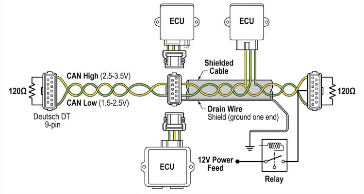
The foundation for all of this—the CAN bus physical layer specifications—define the physical layer requirements we’re testing against, from the 120Ω characteristic impedance to the single-point shield grounding rule.
Step-by-Step: How We Validate J1939 Wiring at the Factory Level
I’m going to give you the exact process we use in our ISO 9001-certified production line. This isn’t a “theoretical best practice.” This is what we do when we build OEM harnesses for agricultural and heavy-duty customers who don’t tolerate field failures.
Step 1: Verify the Physical Layer with a Multimeter—Not Just a Scan Tool
Before you connect a diagnostic adapter, do this:
- Measure resistance between CAN High and CAN Low at the diagnostic connector. With the system powered off, you should read 60 ohms if both termination resistors (120Ω each) are present and in parallel.
- If you read 120Ω, one termination resistor is missing.
- If you read open or very high resistance, you have a broken wire or a bad connection.
- If you read near 0Ω, you have a short between CAN High and CAN Low.
I keep a Fluke 87V in my bag specifically for this. The reason isn’t just accuracy—it’s the Min/Max recording function. When you’re chasing intermittent opens caused by vibration, you can set it to record the minimum resistance over a test drive. That tells you exactly when the connection fails. For accessing the signal lines cleanly during this test, a J1939 9-pin pigtail breakout cable gives you dedicated test points without back-probing connectors.
For a systematic approach to finding these elusive faults, our guide to diagnosing intermittent CAN bus failures walks through the full process.
Step 2: Confirm CAN Voltages with the System Powered
With the key on, engine off:
- CAN High should read between 2.5V and 3.5V relative to ground.
- CAN Low should read between 1.5V and 2.5V relative to ground.
- The sum of the two voltages should be approximately 5.0V.
If you see CAN High stuck at 0V or 12V, you have a short to ground or power. This is often caused by chafed wires where the harness rubs against a frame rail or engine bracket—a failure mode we eliminate in our harnesses by using 125°C cross-linked polyethylene insulation that resists abrasion far longer than standard PVC.
We use a Tektronix TDS2000 series oscilloscope in production for final validation. But for field diagnostics, a decent multimeter with a bar graph (for seeing fluctuations) will catch 90% of issues. For cases where EMI is suspected, our CAN bus shielding and filtering guide provides deeper insight into what the scope reveals.
Step 3: Inspect Termination Resistors—But Not Just Presence
Termination resistors need to be at the physical ends of the bus. Not somewhere in the middle.
On a typical Class 8 truck, one resistor is in the ECM, and one is in the dash panel or diagnostic connector. On agricultural equipment, they’re often in the cab controller and the engine ECU.
But here’s what I see constantly: someone adds an aftermarket module—a telematics unit, an auxiliary display, a backup camera system—and they splice it into the middle of the backbone. Now the bus has three termination resistors, or the termination is no longer at the ends.
The result? Signal reflections that cause random, non-reproducible faults. This behavior is well-documented in the CAN bus physical layer literature, where any impedance mismatch or incorrect termination creates reflections that corrupt data frames.
When we design custom harnesses for customers who add auxiliary equipment, we always provide an inline pass-through with a dedicated stub for additional modules. The stub length is under 0.3 meters (per the J1939-15 standard), and the termination resistors stay at the ends. For installations where space forces the diagnostic connection into a tight dashboard cavity, a J1939 90-degree right-angle Y-splitter cable allows you to maintain a proper stub length while keeping both the vehicle port and diagnostic tool accessible.
Step 4: Power and Ground—The Overlooked Half of the Problem
I’ve lost count of how many times I’ve seen a “CAN fault” that was actually a power supply issue.
Pull the connector off the module that’s reporting faults. Back-probe the power and ground pins. Then:
- Load the circuit. Turn on whatever loads are on that circuit—lights, actuators, whatever shares the feed. Measure voltage again.
- Check voltage drop on the ground side. Put one lead on the battery negative terminal, one on the module ground pin. You want less than 0.2V under load.
- If it’s a relay-controlled circuit, measure voltage before and after the relay contacts. Burned or pitted contacts will show a significant drop.
We test every power circuit in our harnesses with a programmable DC load at 125% of rated current for 30 seconds. If the voltage drops more than 0.3V, the crimp or terminal gets re-done.
Step 5: Shield Grounding—One End Only
The J1939-11 standard calls for the shield to be grounded at one end only. In practice, this means the shield should be connected to chassis ground at the ECU or at a dedicated ground point, and isolated at all other points.
When the shield gets grounded at both ends, you create a ground loop. Current flows through the shield, inducing noise into the twisted pair. This is especially problematic on long vehicles with steel frames—the frame itself becomes a conductor, and the shield becomes part of the ground path.
In our climate-controlled warehouse, every shielded harness goes through a continuity and isolation test: we verify shield continuity end-to-end, then confirm no shorts to any other circuit, and then verify the shield is connected to ground at exactly one point as specified by the customer’s schematic. For high-EMI environments like mining or welding operations, our J1939 ArmorLink vibration-validated cable assembly takes this shielding principle to the next level.
What I’ve Learned Pulling 400+ Harnesses Apart
These aren’t beginner mistakes. I’ve seen these done by technicians who have been in the industry for 20 years.
1. Using the Wrong Twisted Pair
We’ve replaced 47 “professional” harnesses where the installer used 18 AWG primary wire twisted with a drill. The impedance measured 78Ω. The bus margin was gone before the engine ever started.
We use Belden 9842 or equivalent for service replacements. It’s a 22 AWG, 120Ω, shielded twisted pair. Anything else is gambling. Understanding the underlying physics of cable shield, impedance, and jacket specifications is essential to avoiding this mistake.
2. Daisy-Chaining Power Instead of Using a Star Configuration
A 2023 combine came in with all six header controllers dropping offline when the hydraulic fan engaged. The root cause: a single 14 AWG feed daisy-chained through four Deutsch connectors, each with a 0.15V drop. At full load, the last controller was running at 10.8V. The CAN transceiver was brownouting.
3. Crimping CAN Terminals with the Wrong Tool
We pull-test every crimp. When a customer sends back a harness with intermittent faults, the first thing we do is cross-section the terminals. In 80% of field failures, the crimp wings haven’t fully closed—you can see light through the seam. That’s what happens when someone uses a $40 crimper on a $3 terminal.
We use calibrated crimp tools with daily pull-test verification in production. For field repairs, I keep a TE 58495-1 in my kit. It’s designed specifically for the terminals used in J1939 connectors. For a deep dive on why the mechanical connection matters more than most realize, see our analysis of cold weld vs. vibration arbitration in terminal crimps.
4. Grounding Modules to Painted Surfaces
A telematics installer in Nebraska grounded a gateway module to a powder-coated cab mount. The connection read 0.2Ω on the bench. Under load, with vibration, it was open half the time. We now include a dedicated ground stud with a serrated washer in every custom harness we ship.
5. Ignoring the Stub Length Rule
An irrigation system integrator added seven flow monitors to an existing J1939 bus. Each stub was 6 feet long. The bus looked fine on a multimeter—60Ω, proper voltages—but the system dropped nodes every 30 seconds. The stubs created reflections that looked exactly like a missing termination resistor. We replaced the backbone with a pass-through design: each monitor on a 10-inch stub. Zero faults in two seasons.
How to Confirm You’ve Actually Fixed the Problem
Clearing codes isn’t enough. Here’s how we validate repairs:
- Measure resistance again. 60Ω at the diagnostic port after reassembly. If it’s anything else, the repair isn’t done.
-
Monitor bus traffic with a CAN analyzer. Even a basic tool like the CANtact or PCAN-USB with a free software package will show you:
- Bus load percentage (should be under 60%)
- Error counters (should be zero)
- Active nodes (compare with what should be present)
- Perform a wiggle test. With the system powered and the scan tool monitoring, wiggle every connector, bundle, and section of harness you touched. If the fault appears, you missed a connection.
- Drive cycle or operational test. The equipment needs to go through its full operating range—temperature, vibration, load. If the fault only appeared when the equipment was working hard, it needs to be tested under those same conditions.
At our factory, every harness goes through a 100% functional test on a custom fixture that simulates the vehicle electrical system. We cycle every circuit, measure every voltage, and verify every communication path. If we find a fault, that harness is tagged, analyzed, and the root cause is logged into our quality management system.
Products We Build That Solve These Problems at the Source
Because we manufacture harnesses for customers who have learned these lessons the hard way, we’ve developed a few product categories specifically to eliminate these field failures.
OEM Replacement Engine Harnesses
We build these to match your original length and pinout. The difference: we use 125°C cross-linked polyethylene instead of standard PVC. In our heat-soak testing, PVC insulation softens at 85°C—well below underhood temperatures during regen cycles. The XLPE doesn’t. We’ve got harnesses with 15,000 hours in a Western Star logging truck that still pass insulation resistance tests.
Custom J1939 Backbone Harnesses
For equipment integrators adding telematics, cameras, or displays: we build backbone harnesses with dedicated stubs, proper termination at the physical ends, and shield grounded exactly where it needs to be—not where it’s convenient. One customer in the mining sector had 32% downtime attributed to CAN faults before switching to our backbone design. That dropped to 3% after the first installation.
Repair Kits for Common Failure Points
Deutsch DT and DTM connectors, pre-crimped with the correct terminals and sealed with the proper backshells. These are the connectors we see fail most often, especially in applications with high vibration or exposure to chemicals.
Custom OEM Harnesses
If you’re manufacturing equipment and you’re tired of field failures caused by harness issues, we work with your engineering team to design harnesses that are optimized for your specific assembly process and operating environment. We hold IATF16949 certification for automotive-grade quality management, and our facility operates under 5S management with climate-controlled warehousing—so your components aren’t sitting in humidity or temperature extremes before they’re assembled.
What we don’t do:
We don’t use scotch-locks. We don’t use electrical tape as a primary sealing method. We don’t ship a harness without a signed test report that includes measured resistance values for every CAN circuit, not just a “pass” flag.
All of our products are built with:
- RoHS-compliant materials
- Full-plastic or overmolded designs where specified
- 100% tested on custom fixtures
- 4-stage quality inspection: incoming components, in-process, final assembly, and outgoing
Frequently Asked Questions
Q: I have a roll of 18 AWG TXL wire. If I twist it with a drill, will it work for a short CAN bus?
A: No. The impedance of twisted TXL wire is around 70–80Ω, not 120Ω. On a short bus, it might seem to work. But the signal margin is gone. Add one more module, or let the temperature rise under the hood, and the faults start. We’ve replaced 47 harnesses where this exact approach failed.
Q: I’m getting 60Ω at the diagnostic port, but the bus still drops nodes when the engine is above 1500 RPM. Is the termination resistor the problem or something else?
A: 60Ω means both termination resistors are present. The issue is likely elsewhere: ground offset, a long stub, or a chafed wire that only shorts under vibration. Use the Min/Max function on your multimeter while someone revs the engine. If resistance dips below 55Ω or spikes above 70Ω, you have an intermittent connection.
Q: A customer added a third-party display that has its own internal 120Ω resistor. Now the bus measures 40Ω. Should I remove one of the existing resistors?
A: Yes. Remove one of the original termination resistors. You want exactly two 120Ω resistors in parallel—one at each physical end of the bus. Three resistors (40Ω) will cause signal reflections and make transceivers work harder.
Q: Why do I see voltage on CAN High and CAN Low with the key off?
A: Some modules stay awake on the CAN bus for a period after key-off. This is normal. Wait 10–15 minutes and check again. If voltage remains, you have a module that isn’t sleeping properly—or someone has wired a module to constant battery when it should be switched.
Q: What’s the maximum length for a J1939 bus?
A: J1939-11 (shielded twisted pair) allows up to 40 meters. J1939-15 (unshielded twisted pair) allows up to 40 meters with shorter stubs. In practice, most vehicles are well under that.
Q: Can I splice into an existing J1939 bus for an aftermarket device?
A: Yes, but the stub length must be under 0.3 meters (about 1 foot). Use a sealed inline connector, not a scotch-lock or a butt splice. And make sure the termination resistors remain at the physical ends of the bus.
Q: What’s the difference between J1939-11 and J1939-15?
A: J1939-11 uses shielded twisted pair and allows longer stubs. J1939-15 uses unshielded twisted pair with strict stub length limits. Most on-highway trucks use J1939-11. Agricultural equipment often uses J1939-15.
Q: How do I test for a ground offset?
A: With the system powered and running, measure voltage between the module ground pin and battery negative. Anything over 0.2V under load indicates a ground problem.
Q: I’ve replaced three Deutsch DT connectors on the same machine in two years. The terminals look clean. What am I missing?
A: Check the backshell. If the wedge lock isn’t fully seated or the seal is damaged, moisture wicks into the terminal cavity. We’ve sectioned DT connectors from agricultural equipment and found corrosion inside the crimp barrel even when the terminal face looked clean. Replace the entire connector assembly, not just the contacts. For a deeper look at how vibration kills these connections, see our crimp vs. solder reliability guide.
Q: I have a vehicle that was in a fire. The harness insulation is melted but the copper looks intact. Can I reuse it?
A: No. The fire has annealed the copper and destroyed the insulation’s dielectric properties. We’ve tested fire-damaged wire that passed continuity tests but failed insulation resistance at 500V. Replace it.
Q: My termination resistors measure 120Ω individually but 65Ω in parallel. Is that acceptable?
A: 65Ω suggests one resistor is out of spec by about 5Ω. In a quiet environment, it might work. In a high-EMI environment like a truck with a high-output alternator, that 5Ω difference reduces common-mode rejection. We replace any resistor that measures outside 118–122Ω.
Q: We’re a small OEM building 50 units per year. What’s your minimum order quantity for custom wire colors and molded connectors?
A: We work with OEMs of all sizes. For quantities under 100 units, we focus on custom harness configurations using our standard wire colors. For custom molding and branded connectors, we typically start at 500 units, but we’ve made exceptions for customers with long-term programs. Send your specifications and we’ll give you a straight answer.
When You’re Dealing with Something That Doesn’t Match the Diagram
Factory schematics are a starting point, not an ending point.
I’ve seen harnesses where the wire colors don’t match the diagram because the original harness was replaced with a service part from a different supplier. I’ve seen termination resistors that were added in the field and tucked into a bundle where no one can find them. I’ve seen diagnostic ports that were relocated to a different dashboard panel and wired with lamp cord.
The physical layer doesn’t lie. Your multimeter and your oscilloscope will show you what’s actually there, not what the schematic says should be there.
When you’re staring at a truck or a piece of equipment that’s throwing random CAN faults and you’ve already replaced three modules, stop. Go back to the wiring. Measure resistance. Measure voltage drop. Check termination. Check ground offsets.
The problem is almost always in the wiring.
Need Help With a Specific J1939 Application?
If you’re working on a vehicle or equipment with communication issues, or if you’re developing a custom harness for a new application, I’m happy to help you work through the details.
We’ve been building heavy-duty harnesses since 2004—before J1939 was widely adopted outside of Class 8 trucks. Our IATF16949 certification covers our entire production line, not just a “quality-assured” section of the facility. The same processes that go into our automotive OEM harnesses go into every repair kit and custom backbone we ship.
Every harness that leaves our climate-controlled warehouse includes a test report with:
- Continuity measurements for every circuit
- Insulation resistance at 500V DC
- Shield-to-ground isolation verification
- Termination resistance at the diagnostic port
- Operator initials and test fixture ID
Reach out directly:
📧 Contact Page: https://obd-cable.com/contact/
Tell me what you’re working on. I’ll give you straight answers. If we can build a harness that solves your problem, I’ll quote it. If you just need a connector, a termination resistor, or a diagram clarification, I’ll point you to the right page.
No sales pitch. No “let me check with my manager.” Just a straight answer from someone who builds these for a living.
About the Author
We’ve been building heavy-duty harnesses since 2004. ISO 9001, ISO 14001, IATF16949 certified facility. RoHS, CE, UL, REACH compliance. We build harnesses for OEMs and service providers who need reliability in the field—not just a part that works on the bench.
This guide reflects the actual processes we use in production: 4-stage quality inspection, 5S management, climate-controlled warehousing, and 100% testing on custom fixtures.
If you found this useful, share it with a technician who’s chasing a CAN fault today. They’ll thank you.
