

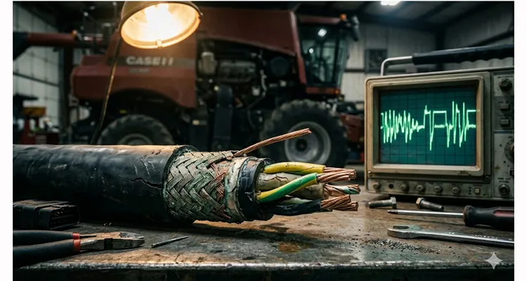
I still remember the cross-section. A J1939 backbone pulled from a Class 8 combine—six months old, OEM harness, no visible damage. We cut it open in the shop under a halogen work light. The braid wasn’t just corroded. It had turned into something that looked like compressed rust wool. The drain wire crumbled when I touched it with a pick. Water had traveled 18 inches up the jacket from a hairline split at the Deutsch backshell.
The farmer had already replaced the ECU and the display. No one had looked at the cable itself—because on the outside, it looked fine. That’s the trap. A J1939 cable can look perfect and still be dead.
That harness cost him $40,000 in downtime. Not because the cable was cheap. Because the cable was wrong for where it lived.
This is what happens when you spec a J1939 cable based on a datasheet instead of a physical environment. I’ve been inside enough engine bays and wiring looms over the past 20 years to know that a spec sheet doesn’t survive first contact with diesel, DEF, or a -40°C cold soak.
This post isn’t about theory. It’s about the metallurgy, the physics, and the manufacturing failures I’ve documented on the workbench. We’re looking at why your cables fail—using real transfer impedance data and material science—so you never have to open another cross-section that looks like rust wool.
The Scene of the Crime: Where J1939 Cables Actually Die
Most engineers spec a cable based on a datasheet. They look at the temperature rating and maybe the gauge. But the field is a different beast. I’ve pulled failed J1939 cables from three distinct environments, and each one tells a different story about how shield, jacket, and impedance break down in ways no spec sheet ever warned them about:
The Engine Bay (Thermal & Fluid Degradation): Inside a Tier 4 Final diesel engine compartment. The ambient temperature cycles from -40°C to 125°C every day. The jacket isn’t just hot; it’s soaked in diesel, hydraulic fluid, and DEF (Diesel Exhaust Fluid). DEF is particularly nasty—it’s a urea solution that crystalizes and eats through cheap PVC jackets like acid through paper. We’ve seen PVC jackets turn brittle in 18 months under these conditions. The failure isn’t slow; it’s a cascade once the first crack appears.
The Articulating Joint (Mechanical Fatigue): On a wheel loader’s steering articulation point. The cable bundle flexes 15 to 20 degrees every cycle. Thousands of times a day. A standard cable with a solid tinned copper drain wire will work-harden and snap in 6 months. The telltale sign? A clean break inside the braid with no corrosion—just metal fatigue, pure and simple. For a deeper look at how vibration and termination quality affect reliability, we’ve documented the differences in field performance.
The Roof (UV & Moisture Ingress): On a forestry harvester or a mining haul truck. The cable is exposed to direct UV radiation. The jacket checks (cracks). Once the jacket cracks, the “capillary effect” pulls water into the braid. This water turns the shield into an antenna, soaking up EMI from the alternator and radio transmitters. I’ve seen braid oxidation wick 24 inches past the visible crack—well beyond where anyone would think to look.
I’ve cut open enough of these to know that when a cable fails, it’s rarely because someone bought cheap wire. It’s because the wire didn’t match the environment it was dropped into.
The Physics of Failure: Impedance, Transfer Impedance, and the Shield
Let’s get into the weeds. If you only take one thing away from this post, remember this: The characteristic impedance (Z0) of the cable must be 120 ohms ± 10 ohms at the frequencies used by the CAN transceiver. That number isn’t arbitrary—it matches the termination resistors at both ends of the bus. Deviate from it, and the network becomes a time bomb.
But why does a cable “drift” from 120 ohms?
It happens when the geometry of the insulation changes. If the insulation material softens under heat and the twisted pair compresses, the distance between conductors changes, altering the capacitance and thus the impedance. When that impedance spikes or drops, you get signal reflections. Those reflections cause bit errors. Bit errors cause the ECU to shut down the network to prevent runaway throttle or brake failure. We’ve traced this exact failure chain more times than I can count. If you’re dealing with intermittent CAN bus faults that won’t reproduce in the shop, impedance drift is often the hidden culprit.
Why Your Alternator Is Broadcasting Through Your Harness
Here is where most aftermarket suppliers get it wrong. The SAE J1939 standard defines a shield to protect the differential pair from external EMI. But the effectiveness of that shield isn’t just about coverage percentage—it’s measured by Transfer Impedance (Zt) .
Transfer impedance is a measure of how well a shield prevents EMI from penetrating the inner conductors. A lower Zt is better. Think of it as the shield’s resistance to letting noise in. A high Zt means your shield is essentially transparent to interference. For a full breakdown of how VFDs and welding equipment couple noise onto CAN lines, we’ve documented the field data separately. The concept of transfer impedance is well-established in electromagnetic compatibility (EMC) engineering as the standard metric for comparing shield performance.
Last year, a customer asked us to validate three “J1939” cables they were sourcing from different suppliers. Same spec sheet on paper. Different behavior on the bench. Here’s what the transfer impedance test showed when we put them on the network analyzer:
| Cable Type | Braid Coverage | Shield Construction | Transfer Impedance (Zt) @ 1MHz | Failure Mode |
| Generic PVC Jacket | 65% | Loose braid + Solid drain wire | ~50 mΩ/m | High EMI susceptibility near alternator. |
| OEM Standard | 85% | Tight braid + Stranded drain | ~15 mΩ/m | Stable for 5-7 years. |
| High-Performance (Our Design) | 95% | Tinned copper braid + Foil + Stranded drain | ~5 mΩ/m | Immune to VFD noise and RF interference. |
Cable A was the one that failed in the field after eight months. Cable B was the OEM baseline. Cable C is what we build when the application involves VFDs, heavy alternator loads, or any environment where EMI isn’t a theory—it’s a fact.
If you are running a J1939 cable next to a Variable Frequency Drive (VFD) for a hydraulic pump, a high transfer impedance cable will drop packets. You need a dual-shielded cable (foil + braid) to get the Zt low enough to survive. That foil layer alone cuts the transfer impedance by an order of magnitude. For a practical guide on hardening diagnostic cables against industrial EMI, we’ve published field-tested shielding strategies.
Step-by-Step: How to Select a J1939 Cable That Won’t Fail
Over the last two decades, we’ve distilled the selection process into a four-step checklist. If you skip any of these, you are gambling with your machine’s uptime. I’ve seen OEM engineers skip Step 2 and pay for it in warranty claims 18 months later. Here’s what we actually check, not what we assume.
Step 1: Define the Thermal and Chemical Exposure
Don’t just say “high temp.” Get the actual fluid list. Pull a maintenance manual. Know what’s leaking onto that cable. We’ve seen “high-temp” rated jackets fail in 12 months because they weren’t rated for DEF.
- PVC: Cheap. Dies in diesel. Hardens in the cold. Avoid for engine bays. We stopped using PVC for off-highway jackets a decade ago. It’s not worth the cost savings.
- PP (Polypropylene): Good for thin-wall insulation on the twisted pair. Low dielectric constant (good for impedance stability), but it melts if you touch it with a soldering iron.
- TPU (Thermoplastic Polyurethane): This is the gold standard for jackets in off-highway. It resists oil, diesel, UV, and stays flexible down to -40°C. It’s expensive, but it saves you from replacing the entire engine harness. We stock TPU compounds specifically for mining and ag applications.
Step 2: Verify the Impedance Profile (Don’t Trust the Label)
A supplier can print “J1939” on a cable even if it uses a 1.5mm thick insulation. You need to see the test report. If they can’t produce it, walk away. We’ve seen labels that say J1939 on cables that failed TDR testing within the first meter.
- Conductor: 18 AWG (0.75 mm²) to 16 AWG (1.0 mm²) stranded tinned copper. Tinned is non-negotiable; bare copper oxidizes inside the insulation over time, increasing resistance. We’ve cut open 10-year-old harnesses with bare copper that had turned black halfway through the run.
- Insulation Wall: The physical thickness of the insulation around each wire determines the impedance. For J1939, the insulation thickness is typically 0.45mm to 0.65mm for 18 AWG. Anything thinner, and the characteristic impedance drops below 110 ohms, putting you outside the CAN spec.
Step 3: Stress the Drain Wire
The drain wire (the uninsulated wire running alongside the braid) is the most common mechanical failure point. I’d estimate 40% of field failures I’ve opened trace back to this single component. It’s the first thing I look at in a failed assembly.
- Solid Drain Wire: Stop using it. It is easier to terminate, but it acts like a spring. Under vibration, it snaps. Every time I see a solid drain wire in a dynamic application, I know I’ll be seeing that harness again.
- Stranded Drain Wire: This is what you want. It flexes with the cable. It costs 15% more to manufacture because we have to run it through stranding machines, but it lasts 10x longer in dynamic applications. That trade-off pays for itself in the first avoided service call.
Step 4: Reject “Split” Jackets
Cut a cross-section of the cable. Look at the jacket wall thickness. This is one test most engineers never run—but once you see the difference, you’ll never unsee it. It’s the difference between a jacket that protects and one that just covers.
- Bad: The jacket is thin over the shield and thick in the valleys. This is a “split” die extrusion. It creates weak spots where the shield pokes through under abrasion. We’ve seen these jackets wear through in under a year on vibrating equipment.
- Good: The jacket is concentric (equal thickness all around). This is achieved with a pressure extrusion tooling. It guarantees the mechanical integrity of the cable. Every cable we run uses pressure tooling—it’s slower, but it’s the only way to ensure the jacket actually protects the shield.
What I Find When I Open a Failed Harness
When I open a failed J1939 assembly on the workbench, I see the same five signatures over and over. These aren’t theory. They’re physical evidence that tells me exactly what went wrong. It’s like reading a crash report, but for a cable.
Impedance Mismatch at the Drop: The harness uses 120-ohm backbone cable but the drop to the sensor is a 100-ohm CAN FD patch cord. Under TDR, you see a reflection exactly at the junction. The network runs fine at idle. At full load, with the alternator at 80 amps, the reflection pushes the signal outside the CAN transceiver’s differential voltage window. The symptom? Intermittent faults that no one can reproduce in the shop. We’ve covered the cost of misdiagnosing J1939 Type 1 vs Type 2 configurations in a separate field analysis.
Shield Used as a Return Path: Someone used the drain wire to carry 12V to a sensor. The shield was never meant to carry current. Now every alternator pulse couples directly onto the CAN lines. I can see it on the scope without even zooming in. The fix is a complete harness redesign—you can’t just “move” the return path. For a comprehensive look at CAN bus shielding and filtering strategies, we’ve documented proper shield termination practices.
Crushed Braid at the Termination: The crimp tool was set too deep. It flattened the twisted pair inside the backshell. The cable passes continuity but fails the TDR test with a sharp dip exactly where the connector sits. Field failures start six to eight months in as vibration finishes what the crimp started. This one is insidious because the cable tests “good” out of the box.
Wet Braid Syndrome: The jacket was rated for “dry locations” but installed on an open chassis. Water wicked up the braid 12 inches past the break. The shield turned into an electrolytic cell. The green corrosion you see inside is the physical signature of this mistake. Once the braid corrodes, transfer impedance goes from 15 mΩ/m to effectively infinite. The port environment failure analysis we published shows exactly how moisture accelerates shield degradation.
CA Cable Masquerading as J1939: The supplier shipped construction automation cable—lower-grade polyethylene insulation—instead of true J1939 construction. It looks the same from the outside. But when the engine bay hits 105°C, the dielectric constant drifts, and the impedance walks right out of spec. We’ve seen this substitution cost customers six figures in warranty claims before they figured it out. The only way to catch it is to test, not trust.
How to Confirm the Fix: Validation in the Field
You’ve replaced the cable. How do you know you actually fixed the problem?
You can’t just look at it. You need to validate the physical layer. These three tests have saved our customers more downtime than any other tool in the box. For a complete methodology, our CAN bus physical layer testing guide walks through the full validation workflow.
- TDR (Time Domain Reflectometry): Use a Fluke or similar tester. Set it for 120 ohms. Send a pulse down the line. If you see a spike or dip in the impedance graph, that’s a physical defect. A clean, flat line means your geometry is correct. We run TDR on every prototype harness before it leaves our shop. It’s non-negotiable.
- The Battery Test: Run a 12V DC current through the drain wire for 30 minutes. If the cable gets warm, your drain wire gauge is too small for the path length, or you have a poor crimp. This test has caught undersized drain wires that passed continuity but failed under load.
- Visual Cut Test: Cut the failed cable open. Look at the shield. Is it oxidized (black/green)? That’s moisture ingress. Is the insulation flattened? That’s thermal compression. Keep a cross-section of every field failure. Over time, it becomes your best training material.
The Hardware That Makes the Connection
We don’t just manufacture raw cable; we build the assemblies that go into these harsh environments. If you are sourcing the physical layer, the cable is only half the battle. The connector interface is where the impedance either holds or falls apart. A perfect cable with a bad termination is a bad assembly.
For J1939, the standard is the Deutsch DT or DTM series. But a “Deutsch” connector isn’t a magic bullet. If the backshell isn’t designed to support the shield termination, you lose all the noise protection you paid for. I’ve seen more field failures from poor shield termination than from bad cable itself.
In our factory, we treat the shield termination as the highest critical control point. We operate under IATF 16949:2016 and maintain ISO 9001 quality systems. We use a 4-step quality inspection on every J1939 assembly:
- Conductor Crimp: Pull test to ensure the core crimp holds. We log every pull test value by batch.
- Shield Ferrule Crimp: We use a hex crimp on a copper ferrule to establish 360° shield contact to the backshell. A “pig-tail” (soldering a wire to the shield) is a hack; it kills the low transfer impedance. We don’t do pig-tails. Period.
- Impedance Match: We verify the crimp zone does not alter the 120-ohm characteristic. If the impedance shifts more than 5 ohms in the termination zone, we adjust the tooling.
- 100% Hi-Pot & Continuity: Every single cable goes through a high-potential test before it goes into the climate-controlled warehouse. No sampling. No spot checking. Every assembly.
We are a direct factory with 20+ years of experience. We don’t stock “one-size-fits-all” cables. We stock raw materials—tinned copper stranding, TPU compounds, and Deutsch contacts—and build to your spec. When you order from us, you’re not getting something off a shelf. You’re getting a cable built to your environment.
If you need a specific length, a specific over-mold shape, or a custom logo on the jacket for your fleet, we do that in-house. We operate under 5S management. The floor is clean, the temperature is controlled, and the crimp pressure is logged for every assembly. We can trace every crimp back to the operator, the tool, and the date.
Frequently Asked Questions
Q: What happens to characteristic impedance when the cable is routed through a metal bulkhead without proper grommet support?
A: The impedance drops at the pinch point. If the compression reduces the insulation thickness by 20%, you can see a 15-ohm dip. That’s enough to corrupt the recessive bit detection. We use a TDR scan on prototype harnesses to identify these bulkhead pinch zones before first article approval. It’s cheaper to move a grommet than to recall 500 harnesses.
Q: Can you terminate a J1939 shield to chassis ground at both ends?
A: You can, but you’ll create a ground loop. The shield should be terminated at one end only—typically the ECU side—unless the application uses a 360° circumferential bond that eliminates potential differences. We specify single-point grounding unless the customer provides a verified grounding architecture drawing. Ground loops are one of the hardest intermittent faults to diagnose. For a deeper look at grounding and shielding in harsh environments, we’ve documented field-proven approaches.
Q: How do you verify shield continuity after overmolding?
A: We test with a milliohm meter before and after overmolding. A change greater than 5 milliohms indicates the shield ferrule moved during the injection process. That assembly goes to the scrap bin. We keep a log of every test for traceability. Overmolding is where good cables go bad if you don’t control the process. Our ArmorLink vibration-validated assemblies are built specifically for high-vibration environments where overmold integrity is critical.
Q: Can I use CAT5e Ethernet cable for a J1939 backbone?
A: Technically, the impedance is similar (100 ohms vs 120 ohms). But mechanically? No. CAT5e has solid conductors that snap under vibration. The jacket is not oil-resistant. If you do it for a prototype in the lab, fine. In a truck? You’ll be replacing it in 90 days. We’ve seen this attempted more times than I’d like to admit.
Q: What is the difference between J1939-11 and J1939-15?
A: This is the physical layer specification. J1939-11 is the “shielded” standard (the one we are discussing). J1939-15 is the “unshielded” standard for low-cost, non-critical applications. If you are in heavy equipment, stick with -11. The shield is worth the cost. I’ve never seen a heavy equipment application where unshielded worked long-term.
Q: How do agricultural environments specifically affect J1939 cable longevity?
A: Agricultural applications combine all three failure modes—chemical exposure from fertilizers and DEF, mechanical flex from articulated steering, and UV exposure in open fields. We’ve published a dedicated J1939 cable agricultural survival guide that breaks down field-tested material selections for tillage, spray, and harvest equipment.
If you’re sourcing J1939 assemblies and the only difference between suppliers is the price, you’re not buying a cable—you’re buying a future field failure. I’ve watched customers chase that savings straight into a warranty hole they couldn’t climb out of. The real cost is never the cable; it’s the downtime.
We manufacture under IATF16949. We log crimp pressures. We test shield ferrule integrity. We stock TPU compounds, tinned stranding, and Deutsch contacts—and we build to your drawing, not a catalog page. When you send us a drawing, we build exactly that. No substitutions. No “similar enough.” For OEM engineers, our checklist for EMI-hardened diagnostic cables outlines the specifications we validate on every assembly.
If you want to talk through a specific environment—an engine bay with DEF exposure, a mining truck with VFD noise, a forestry machine with constant flex—send your BOM or a sketch. We’ll tell you where the standard spec will fail and how we would build it differently. No sales pitch. Just engineering.
📞 Chat with our engineering team on WhatsApp: Click here to chat with Linda
✉️ Send us your BOM or drawing for a technical review: Visit our Contact Page
We are a direct factory. We specialize in OEM customization—logo, length, color, and AWG. All products are RoHS, CE, and UL compliant. No minimum order quantity for engineering samples.
