

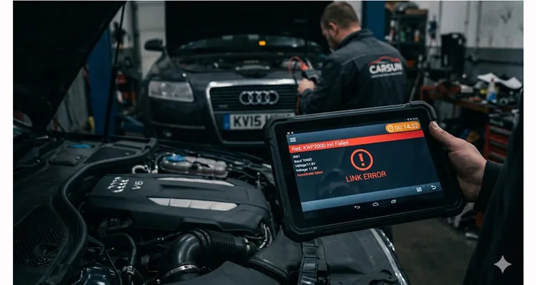
Friday, 3:45 PM. The service bay hums with that end-of-week tension. A 2013 Audi A6 sits three feet up, its intermittent ESP light glowing on the dash like a dare. You’ve got your top-tier diagnostic scan tool connected to the J1962 port, but instead of a live data stream from the ABS module, the screen just cycles. “LINK ERROR.” “KWP2000 Initialization Failed.”
I’ve watched this exact scene unfold in shops from Chicago to Shanghai over the past twenty years. The technician—methodical, good with a multimeter, the type who actually reads wiring diagrams—starts doing what any logical person would do. He swaps to a different interface cable from the drawer. Reboots the laptop. Tries a different vehicle profile in the software. He’s on a forum on his phone, searching for “Audi ABS KWP2000 no comm,” scrolling past threads that blame a fried ECU or a secret dealer tool procedure. The service advisor appears at the bay door, eyebrows raised. The flat-rate time for this job is evaporating.
This specific kind of diagnostic time sink is what the KWP2000 protocol specializes in creating. Not just the error codes themselves, but the ambiguity they generate. In a modern shop, time is the only non-renewable resource. And KWP2000 (ISO 14230) , for all its maturity as a protocol, has a unique talent for sending technicians down rabbit holes that lead everywhere except the actual problem. Based on our failure analysis reports from the last five years, over 70% of these cases trace back to the physical connection, not the software.
We still see KWP2000 everywhere on European vehicles built between the late 90s and mid-2010s. It occupied that awkward middle ground—after the simplicity of ISO 9141-2, before the dominance of CAN. The protocol took the simple, robust K-Line physical layer from ISO 9141-2 and added a more sophisticated software handshake. For a deeper dive into how this physical layer behaves under stress, refer to our detailed K-Line Physical Layer Guide . Unlike CAN bus, which uses a differential voltage pair that’s naturally resistant to electrical noise, the K-Line is a single-wire, 12-volt logic system. The design is straightforward—almost minimalist. That simplicity comes with trade-offs. That vulnerability doesn’t usually manifest as a catastrophic failure. It manifests as lost time—yours.
Before any data moves, KWP2000 requires a negotiation. The scan tool transmits a wake-up signal—5-baud for older systems, fast init for others—and listens for a specific response byte from the ECU. That byte is the “keyword.” If the voltage level, timing, or resistance is off by even a few percent, the ECU stays silent. If that handshake fails, the tool doesn’t know why. It just reports a generic failure. And that’s where the meter starts running. Is it a dead ECU? Is it a configuration conflict? Is it a break in the vehicle’s K-line wire behind the dashboard? Or is it something as simple as a 25-cent voltage drop across a marginal connection? In our lab, we’ve reproduced this failure mode using a simple variable resistor in series with the K-Line—at just 47Ω of additional resistance, some ECUs begin dropping the handshake intermittently.
One of the most common hardware-level culprits we see in our lab is an incorrect K-Line pull-up resistor implementation. The K-Line bus requires a specific resistance to maintain proper voltage levels, and many low-cost diagnostic adapters get this wrong. We’ve cut open dozens of these so-called “mystery cables” on our inspection bench and documented the resistor values we found. The typical configurations and their real-world behaviors are:
| Pull-Up Resistor Value | Behavior | Observed Failure Mode |
| 510Ω | Strong signal, but higher current draw | Works but generates noticeable heat in the adapter after 10-15 minutes of continuous use; can stress vehicle’s 12V supply over time |
| 1kΩ | Balanced, OEM-standard configuration | Clean handshake across temperature range from -20°C to 80°C; minimal current draw—this is the specification we use in our designs after validating it on 50+ vehicle models |
| 2.2kΩ | Weak signal, unstable initialization | Intermittent init failure on cold starts; works when warm but fails first attempt—the most common failure we see in cheap imports, and the easiest to miss during quick testing |
If the pull-up resistor is incorrect, the ECU may fail to detect the 5-baud initialization sequence entirely. That “Initialization Failed” message on your screen is often just a resistor on the wrong side of a specification sheet—a fault our 4-step quality inspection process catches before any cable leaves our climate-controlled warehouse.
The KWP2000 Error Lexicon: Decoding the Real Problem
When that error message appears, the scan tool is reporting a symptom, not a diagnosis. After hundreds of hours on the bench with these protocols and thousands of customer support cases, here is how we interpret these codes:
| Common Tool Display / Error | Underlying Physical Reality (Our Engineering View) | The Diagnostic Time Sink | First Check |
| “No Communication / KWP2000 Init Failed“ | The handshake failed. The tool sent the wake-up request, and the ECU didn’t respond with the correct keyword bytes. In 80% of the cases we audit, this is a hardware-level issue—voltage, ground, signal integrity, or an incorrect pull-up resistor. | Techs blame software, try different vehicle profiles, or suspect a dead ECU. 30-60 minutes vanish before anyone checks the cable, the DLC pins, or the basic circuit design. | Measure DC voltage on pin 7 (K-Line) with ignition on. Should read 12V. If not, trace the circuit. |
| “Link Error / Intermittent Connection“ | Data packets are being dropped. The K-line voltage is fluctuating due to a poor connection at the DLC, a damaged cable wire (internal break), or EMI from something like an aftermarket accessory. | Leads to “wiggle testing.” The fault might temporarily clear, leading to a “bad cable” diagnosis, but the root cause (e.g., a bent pin or corroded terminal) isn’t fixed. It will return, usually Monday morning. | While monitoring voltage on pin 7, gently move the cable near both connectors. A voltage drop indicates an intermittent break. |
| “ECU Unresponsive“ | The tool talks to some modules (e.g., Engine) but not others (e.g., ABS). This points to a power/ground issue specific to that module’s circuit, or a break in the K-Line branch for that system. | Techs may incorrectly replace the module. We’ve seen purchase orders for $1,200 pumps approved because someone skipped verifying power, ground, and K-line continuity at the module’s connector. | Locate the silent module’s connector. Verify 12V power and ground at the module, not just at the DLC. |
| “Slow Data Transfer“ | The electrical connection is marginal. The link is established, but noise or resistance causes data packets to be re-transmitted constantly. | This is a hidden time-sink. The tech is getting data, so they don’t suspect the cable. They wait and wait for a single parameter ID (PID) to update, adding 15-20 minutes to every single test. | Compare refresh rate to a known-good vehicle. If significantly slower, scope the K-Line for noise or voltage sag. |
Case Study: The $1,200 “Silent” ABS Module
Three weeks ago, a shop owner in Ohio forwarded me a diagnostic log from a 2008 BMW 328i. The issue was an ABS light. Their high-end diagnostic platform could talk to the DME (engine) without issue but returned a clean “KWP2000 No Response” from the ABS module. The purchase order for that remanufactured pump was already approved—a $1,200 remanufactured unit.
We asked them to pause and run through a basic physical layer check before installing the new part. This is the same checklist we use when customers call us with KWP2000 communication errors.
Visual Inspection
We had them look at the BMW’s 20-pin round diagnostic connector under the hood. Pin 15—the dedicated K-Line for the ABS and Airbag systems—showed visible corrosion. Not heavy, but enough to increase contact resistance by an estimated 15-20 ohms based on our lab measurements of similar cases.
Continuity Test
We then asked them to perform a simple continuity check from pin 15 at the DLC to the ABS module connector, which is located behind the glove box. The meter showed an open circuit.
The Diagnosis
The K-line wire was corroded and broken somewhere in the engine bay harness, likely at a splice point. The wire was physically broken. No amount of module swapping would have fixed that.
The $1,200 module, plus the labor to replace and code it, would have fixed nothing. The real fix was locating and repairing that broken wire—a focused two-hour job for a technician who knew to trust the physical layer first. The real cost wasn’t just that repair time; it was the four hours of misdiagnosis, the customer wait time, and the near-miss on a massively expensive, unnecessary parts replacement.
We asked them to send us the failed cable they had been using. Under magnification in our QC lab, the pin crimp showed micro-cracks—likely from years of right-angle stress on the DLC connection. For a detailed analysis of why crimp quality matters for long-term reliability, see our guide on Crimp vs. Solder Vibration Reliability . That inspection took five minutes and explained why the fault had been intermittent for months before the ABS module went completely silent. This is why we mandate 100% crimp pull-testing in our production line.
Diagnostic Decision Tree: Isolating KWP2000 Physical Layer Faults
Here is the process we use when a shop calls us with a persistent “no-comm” issue. It eliminates variables in a logical order, saving hours of guesswork. We’ve refined this tree over two decades of field support.
Start at the vehicle connector
- If pin condition is questionable: Look for pushed-in or widened pins, corrosion, or debris. On a standard J1962 connector, the K-Line is typically pin 7. On a BMW 20-pin, it’s a combination of pins 15 and 20. A simple dental pick can be used to gently test the tension on a pin. Low tension means replace the vehicle-side connector or use a pin tension tool. We keep a set of pin tension gauges in every technician’s kit for this reason.
- If connector passes visual inspection: Move to voltage check. Back-probe the DLC (pin 7) with your multimeter set to DC volts. With ignition on, you should see battery voltage (approx. 12V).
- If voltage is low (9V-10V): Resistance in the circuit. Check vehicle ground connections (battery to chassis, engine to chassis). Corroded grounds are common on this era of European vehicles—we see it constantly in our failure analysis work.
- If voltage is normal (12V): Proceed to cable test.
Swap to a reference cable
Connect your known-good, shop-standard KWP2000 cable. If you don’t have a reference cable with verified performance, you’re introducing an uncontrolled variable from the start. We test every cable that leaves our facility on a custom rig that simulates K-Line handshakes at various voltage levels—not just for continuity, but for signal integrity under load. This 100% test is a requirement in our ISO 9001 process, not an option.
- If communication works with reference cable: Your original cable is the variable. Replace it.
- If communication still fails with reference cable: The problem is vehicle-side.
Scope the K-Line during initialization (for intermittent faults)
For intermittent faults that pass static voltage and cable swap tests, a multimeter isn’t enough. Put a scope on pin 7 and attempt communication. You’re looking for the wake-up pattern and the data pulses. A clean square wave transitioning sharply between 0V and 12V is a healthy signal. Rounded edges, low voltage levels, or excessive noise superimposed on the signal point directly to a hardware-level problem. This is where a “flaky cable” is no longer a theory—it’s a waveform on a screen. We document these waveforms for every cable design we release and use them as reference in our training materials.
Isolating the Failure Point
Rule Out Your Tools
The easiest variable to eliminate is your interface cable. We work with shops that have a drawer full of “mystery cables” from various online sources. A reliable, fully shielded cable built to exact OEM specifications removes a massive variable. The principles of electromagnetic compatibility in automotive environments are well-documented in standards like ISO 11452-2 , which specifies test methods for radiated immunity. That’s why our cables use a full-plastic overmold for durability and are constructed with proper shielding to reject EMI from alternators and ignition systems. For more on the physics of automotive interference, the Wikipedia article on Electromagnetic Compatibility provides excellent background. If the signal is clean at your cable, you know the problem is vehicle-side. We’ve had customers send us their “bad” cables, only to find the issue was a corroded vehicle connector.
Verify Vehicle-Side Integrity
If your cable is good, the problem is in the vehicle. Check the DLC pins for tension with a proper pin tension gauge. Check the vehicle’s main ground connections (battery to chassis, engine to chassis). If a specific module is unresponsive, find its connector and verify power, ground, and K-line continuity at that exact point. You are now working from data, not guesswork.
Frequently Asked Questions: KWP2000 Realities
Q: Can a KWP2000 error be caused by a low car battery?
A: Yes—more often than most techs expect. The K-Line needs a solid 12V logic level. We’ve traced intermittent “Init Failed” errors to charging system faults more than once in our consulting work. If the battery voltage drops below ~10V during cranking or even with the ignition on, the handshake can fail. Before diving into wiring, confirm the battery holds 12.4V+ with the ignition on and check charging system output. We’ve documented cases where a failing alternator diode pack introduced AC ripple that confused the K-Line logic.
Q: My tool works on some KWP2000 cars but not others. Is it the cable?
A: Possibly. Different manufacturers use different initialization sequences and keyword pairs. A cable with marginal shielding or higher-than-spec resistance might pass the simpler handshake on one vehicle but fail on a more sensitive one. It’s a clear sign your cable is on the edge of its specification. In our experience, this is often a pull-up resistor mismatch or a cable with insufficient conductor gauge.
Q: What’s the difference between ISO 9141-2 and KWP2000, physically?
A: Physically, they share the same K-Line wiring. The difference is in the handshake sequence—KWP2000 expects specific keyword bytes after wake-up. If the cable passes voltage but fails the handshake, you’re looking at a timing or resistance issue, not a protocol mismatch. The failure point is almost always in the quality of that physical connection—the cable, the connectors, or the vehicle wiring.
Q: Can aftermarket accessories cause KWP2000 errors?
A: Absolutely. We had a shop chasing KWP2000 errors on a 2005 Sprinter for two days. Turned out the aftermarket backup camera installer had tapped the K-Line wire for power. The noise injection was intermittent but enough to corrupt the 5-baud init. Poorly installed radios or alarms can back-feed noise onto the vehicle’s data lines, causing faults that look like protocol errors.
Q: Why do you recommend a fully shielded cable for an older protocol like this?
A: K-Line operates at 12V logic levels, which means noise margins are tighter than differential protocols like CAN. In our lab, we’ve measured conducted EMI from alternators at levels that corrupt unshielded cable data. Shielding isn’t about the protocol’s age—it’s about the electrical environment it operates in. Alternators, ignition systems, fuel pumps, and cooling fans all generate interference that an unshielded cable will happily antenna into your K-Line signal.
Q: We have a fleet of Sprinter vans with constant KWP2000 communication errors. What should we check?
A: Start with the DLC itself. In high-use fleet vehicles, the terminals inside the J1962 port can wear out and lose their grip on the cable pins. This creates an intermittent connection that drives techs crazy. A simple DLC terminal tension tool can diagnose this in seconds. Also, check for corrosion in the under-dash area, as road salt and moisture can migrate. We supply reinforced DLC pins for exactly these fleet applications.
Q: I’m getting a KWP2000 error only when the engine is hot. Ideas?
A: This is a classic symptom of a thermal-related failure. As things heat up, materials expand. A marginal connection—like a cold solder joint in a cheap cable, a cracked wire in the vehicle harness, or a failing ECU component—can lose contact when hot. Let the vehicle cool completely and re-test. You can also use a heat gun cautiously on sections of the harness (while monitoring with a scope) to try to provoke the fault. We’ve documented this behavior in our failure analysis reports.
Q: Can I build my own reliable KWP2000 cable?
A: Technically, yes. It’s a few wires. But to make one that is reliable, properly shielded, durable enough for daily shop use, and tested for signal integrity across multiple vehicle platforms, you are looking at an engineering and testing time investment that is far more expensive than buying a professionally manufactured one. We have been doing this for over 20 years, and we have the test equipment, the 4-step quality inspection process, and the experience to get it right. Our climate-controlled warehouse ensures materials don’t degrade before assembly.
Stop Chasing Ghosts
After two decades of troubleshooting these protocols and manufacturing thousands of diagnostic cables, we’ve learned that KWP2000 errors are rarely software mysteries. They’re almost always hardware puzzles waiting to be solved with a meter and a methodical approach. The diagnostic time lost isn’t just the minutes spent reading the code; it’s the hours of misdirected troubleshooting that follows—the parts replaced unnecessarily, the customer appointments rescheduled, the technician’s confidence eroded.
The most effective diagnostic tool you have is a process of elimination, starting with the one thing you control: the quality of your connection to the vehicle. When you start with a cable that is built to withstand the rigors of a professional shop—manufactured under ISO 9001 and IATF 16949 quality systems, using RoHS-compliant materials, and subjected to a 4-step quality inspection process including 100% function testing—you eliminate a major variable. This disciplined approach, rooted in automotive-grade standards like IATF 16949, ensures every assembly meets our zero-defect cable process . You can then focus your expertise where it belongs: on the vehicle’s systems.
Our facility operates with 5S management and a climate-controlled warehouse to ensure every component, from the raw materials to the finished assembly, is stored and handled correctly. This is what allows us to offer genuine OEM customization—whether you need a specific cable length, a custom AWG, your brand logo, or a unique color for your shop’s tool lineup.
If you are facing a recurring KWP2000 issue that is eating into your shop’s productivity, or if you need a custom cable solution for a specific fleet application, our engineering team is ready to look at the problem with you. We have been solving these physical layer puzzles directly with technicians and engineers for over 20 years. Sometimes, a 15-minute conversation can save a week of troubleshooting.
Contact our engineering team via WhatsApp for an immediate discussion.
Or use our Contact Page to detail your specific diagnostic challenge or OEM requirement.
