

The bay is clear. You’re deep into a mandated DPF regeneration trace on a quarter-million-dollar hauler, the data stream inching toward a ghost code that’s cost weeks of downtime. Then—crack-hiss. The adjacent stall’s arc welder fires. Your screen stutters, freezes. “Link Lost.” The cycle aborts. You’ve just burned thirty minutes of labor and triggered a forced regen that will waste 5 liters of fuel and delay revenue service by an hour. This is no glitch; it’s electromagnetic assault with a direct line to your bottom line.
In the trenches of heavy industry—where mining shovels, construction cranes, marine engines, and agricultural harvesters operate—the OBD2/J1939 port is the central diagnostic nervous system. When high-energy equipment like welders, magnetic lifts, or industrial VFDs cycle on, they don’t just disrupt the peace; they flood the area with wide-spectrum interference that overwhelms the delicate differential signals of the vehicle’s Controller Area Network (CAN) bus. The result is unambiguous: failed diagnostics, corrupted ECU flashes, and downtime measured in hard costs.
The core issue is a mismatch of environment and design. Off-the-shelf diagnostic cables are built for the controlled, quiet bay of a passenger car dealership. They fail catastrophically here. The solution isn’t a gimmick or a magic box; it’s a systems-level understanding of EMI shielding, applied with forensic rigor to the entire cable assembly. Let’s move past spec sheets and discuss what truly preserves a data link when the industrial environment is hell-bent on destroying it.
Why Your Diagnostic Link Goes Deaf in a Noisy Room
The failure mode is predictable and repeatable. These are the primary interference sources in an industrial setting:
- Arc Welding & Plasma Cutting: The initiation of a high-current arc creates a violent, broadband radio frequency (RF) burst—a near-instantaneous high-intensity event that electromagnetically blankets the entire area.
- Large Motor Start-Up: The massive inrush current to spin up a conveyor belt or a large hydraulic pump motor generates a powerful, transient magnetic field, a classic electrical transient.
- On-Board Radio Transmitters: High-power two-way radios, standard in logistics and mining, can directly couple noise onto nearby wiring harnesses, acting as potent, localized transmitters.
- Poorly Shielded Industrial VFDs: The stealth culprit on much mobile equipment. These drives are prolific EMI generators. Beyond their internal switching frequency noise, their cooling fans can pull EMI-laden air across electronics, and their cabinets can act as resonant cavities, re-radiating interference. Crucially, the worst jamming often occurs during acceleration or deceleration, as the switching harmonics sweep directly through the vulnerable CAN bus bandwidth.
The symptom is never subtle. Communication drops entirely, or the data stream dissolves into chaos the exact moment the interfering device activates. A standard, unshielded cable acts as a perfectly tuned antenna, harvesting this RF chaos and piping it directly into the sensitive transceivers of your scan tool or gateway module. If you’re tracing an elusive, intermittent failure, our guide on how to diagnose intermittent CAN bus failures provides a complementary frontline troubleshooting methodology.
The Physics of the Failure: It’s Not Just Radio Waves
Building a robust defense requires understanding the attack. The CAN bus is inherently noise-resistant, using a differential signal (CAN_H and CAN_L) across a twisted pair. The twist excels at rejecting common-mode noise—interference affecting both wires equally—making it highly effective against low-frequency, far-field noise. A foundational first step in any diagnostic sequence is a CAN bus health check with a multimeter to rule out basic network faults before confronting EMI.
Industrial EMI is a different animal: high-intensity, near-field, and broad-spectrum. While airborne radiated noise is a factor, the primary assassin in a workshop is near-field magnetic coupling. Picture the welder’s stinger cable as the primary winding of a transformer. Your diagnostic cable, lying parallel on the same cart, becomes the secondary winding. The intense magnetic field from the welding current induces a voltage directly into your cable loop. The twisting in a standard CAN pair, designed for far-field rejection, is utterly overwhelmed by this intimate, high-power magnetic embrace. This is why simply shifting the cable a few feet sometimes “fixes” the issue—you’ve moved out of the strongest field lines. This type of coupling is one of the four fundamental electromagnetic interference (EMI) coupling mechanisms.
This physics also explains the total failure of the cheap foil shield on commodity cables. If that foil isn’t 100% sealed at the connectors (a near-universal flaw), the gap itself acts as a slot antenna, potentially resonating and amplifying interference at specific frequencies.
Engineering a Solution: A Forensic, Layered Defense
You cannot silence the EMI at its source in a working yard. The only viable strategy is to harden the data path. This demands a military or aerospace-grade layered approach to cable design, where each stratum is engineered to defeat a specific failure mode documented in our years of field returns and teardown analysis. This philosophy is integral to our IATF 16949 PPAP zero-defect cable process for critical automotive components.
Layer 1: The Outer Jacket & Physical Defense
- Material: Oil-resistant, high-abrasion PVC or Polyurethane (PUR). This layer isn’t for shielding; it’s for survival against hydraulic fluid, solvents, and service carts.
- Critical Detail: Bonded or Overmolded Strain Relief. The jacket must be bonded or overmolded directly to the connector backshell. Any gap is a guaranteed flex failure point and a potential ingress for conducted noise.
Layer 2: The Primary Shield (Braid) – The Magnetic Field Workhorse
- Material: High-density, tinned copper braid with ≥85% coverage. The tin plating is non-negotiable to prevent oxidation, which would increase shield resistance over time.
- Function: High-Frequency Magnetic Field (H-Field) Suppression. The braid’s low inductance creates a low-impedance path to ground for induced currents, shunting them away from internal conductors before they disrupt the signal. Its flexibility is critical for long-term cable durability.
Layer 3: The Secondary Shield (Foil) – The Electric Field Seal
- Material: Aluminum-polyester laminate foil with a continuous drain wire.
- Function: High-Frequency Electric Field (E-Field) Suppression. This foil provides 100% coverage, acting as a seamless barrier that seals microscopic gaps in the braid. The polyester laminate prevents micro-cracking during flexing.
Layer 4: The Internal Core – Signal Integrity
- Precision Twisted Pair: The CAN_H/CAN_L wires must be twisted to a tight, consistent specification (e.g., 20 twists per meter) to preserve the differential pair’s inherent noise immunity.
- Individual Wire Shielding (For Critical Applications): In extreme environments—proximity to radar or comms masts—each signal pair may need its own internal foil shield to prevent cross-talk (e.g., isolating K-line noise from CAN).
- Mechanical Integrity: Aramid yarn fillers for crush resistance; a ripcord for clean termination without shield damage.
Layer 5: Connector Termination & Grounding – The Critical Link
All preceding layers are invalid without perfect grounding. Our forensic analysis shows 90% of field failures originate here. A flawed termination is a top cause of OBD2 port no communication issues.
- 360° Circumferential Termination: The braid and foil must be clamped circumferentially to the connector’s metal shell. Pigtailing the shield adds fatal inductance, rendering it ineffective at high frequencies. We confirmed this by testing a competitor’s pigtailed cable: at 27 MHz (marine band), the shield impedance was so high it was electromagnetically invisible. For a deep dive on termination reliability, see our analysis of crimp vs. solder for vibration reliability.
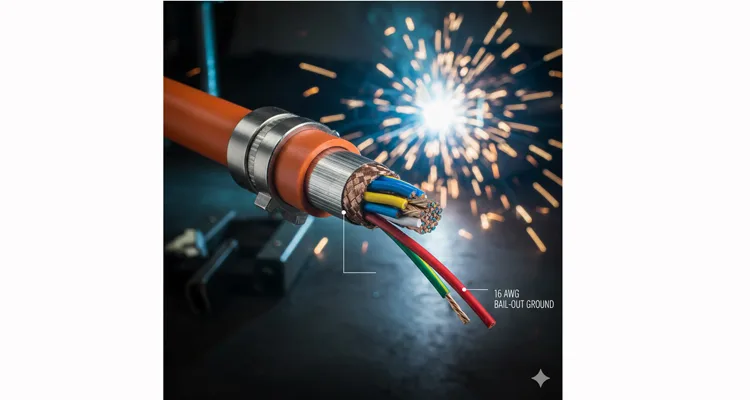
- Clean Ground Path: The connector shell must have a low-resistance, metal-to-metal connection to the vehicle’s chassis ground. Paint or corrosion here is a single point of failure. Our design includes a dedicated 16 AWG ground wire as a “bail-out” to a verified chassis point.
- Strategic Ferrites: A properly specified ferrite bead or clamp adds impedance to common-mode noise without affecting the differential signal. This is a supplemental filter, not a replacement for proper shielding.
Shielding Effectiveness: A Data-Backed Comparison for Engineers
| Shield Type | Typical Coverage | Best At Suppressing | Weakness in Industrial Settings |
| Single Foil (Aluminum) | ~100% | High-frequency E-fields (e.g., radio). | Brittle. Fails with flex. High transfer impedance if terminated poorly. Acts as a slot antenna. |
| Single Braid (Copper) | 60-85% | Low-frequency magnetic fields (motor start-up). Good physical durability. | Gaps allow RF leakage. Weak against very high-frequency E-fields. |
| Foil + Braid (Combination) | 100% + ≥80% | The Professional Solution. Braid handles H-field, foil handles E-field. Durability of braid protects the foil. | Higher cost. Total reliance on perfect 360° termination. A poorly executed combo shield is worse than a good single braid. |
*Note: Transfer impedance (lower is better) is the definitive metric for shield performance, quantifying how much noise “leaks” through. Data derived from in-house testing per IEC 62153-4-3 in our EMC lab, part of our commitment to standards like GB/T 24001-2016 / ISO 14001:2015 environmental management. Real-world performance is contingent on termination quality.*
Five Common (and Costly) Mistakes to Avoid
- Pigtailing the Shield. This transforms your shield into a single-turn inductor, ineffective above a few MHz. Always insist on 360° circumferential termination. It’s non-negotiable.
- Confusing Jacket Thickness for Shielding. A thick jacket only adds abrasion resistance. The shield is a separate, conductive layer underneath the jacket.
- Ignoring Connector Grounding. A floating shield (not grounded) can resonate and amplify noise. Verify the OBD2 port housing has a solid chassis bond.
- Using Uncharacterized Consumer Ferrites. Off-the-shelf ferrites are not characterized for the CAN bus frequency band (e.g., 250 kHz for CAN, 500 kHz for J1939). Use specified common-mode chokes designed for data lines.
- Neglecting Cable Routing. Running parallel to welding leads or AC power lines maximizes inductive coupling. Cross these sources at a 90-degree angle.
How to Validate Your Fix: A Field-Grade Protocol
Move beyond “it seems okay.” Validate with empirical data:
- Monitor CAN Error Frames: Use your diagnostic tool’s bus monitoring. Induce interference (e.g., start an overhead crane). A properly shielded cable will show less than 5 error frames per minute. A standard cable may spike to hundreds.
- Oscilloscope Signal Integrity Check: The gold standard. Use a differential probe, trigger on a specific CAN ID. At a collapsed timebase, inspect the rising and falling edges. With a good cable, edges are clean, ringing contained within 10% of the bit level. We provide these reference waveforms to OEM partners. For multimeter basics, see our CAN bus multimeter fault tracing guide.
- Reproducible Stress Test: Intentionally recreate the failure. Have a welder operate at a set distance (e.g., 3 meters). The diagnostic link must remain stable with error counts within the passing threshold.
The Tool for the Job: An Engineered Interface, Not a Commodity
When your environment features 1000-amp welding rigs and 500-horsepower dynamometers, your diagnostic cable is a critical interface component, not a commodity. It must be engineered with commensurate rigor. Understanding the true cost of a custom cable is essential for this capital decision.
Our Industrial-Grade J1939/OBD2 Diagnostic Cables are built from this forensic philosophy. To defeat near-field magnetic coupling, we specify a minimum 85% coverage, tinned copper braid with a characterized transfer impedance curve. The nickel-plated connector shell prevents galvanic corrosion, ensuring the clean ground path lasts. The 16 AWG silicone-insulated ground wire is a “bail-out” for when the vehicle’s ground point is a painted panel 18 inches away. This durability is paramount for applications like J1939 cable survival in agriculture.
We provide engineering validation data—shielding effectiveness graphs, transfer impedance plots—because capital decisions require more than claims.
OEM & Customization Supported: Need a specific length, custom pinout, a molded connector for your test rig, or a specific ferrite characteristic? This is our specialty. We translate your unique EMI profile and physical challenges into a reliable cable specification, manufactured under our IATF 16949 and ISO 9001 processes. Every unit undergoes a 4-point inspection.
FAQ: Answering the Direct Questions
Q1: Will this cable work with my generic ELM327 Bluetooth dongle?
A: It will physically connect and protect the signal to the dongle. However, the primary vulnerability often becomes the dongle itself, with minimal internal filtering and a cheap PCB antenna. For critical work, pair our cable with a ruggedized interface.
Q2: My fleet has both 12V and 24V systems. Is the cable compatible?
A: Absolutely. Signal lines (CAN, K-line) use identical low logic-level voltages. The cable is voltage-agnostic. The key is pinout compatibility between the vehicle’s J1939 or J1962 port and your tool. Reference our J1939 connector pinout guide for details.
Q3: How do I properly ground the connector?
A: Our cables include a ground wire pre-terminated to the connector shell. Attach it under a clean, unpainted bolt on the vehicle chassis. Use a star washer or scrape paint for metal-to-metal contact.
Q4: Can you make a cable that also powers my tablet from the vehicle?
A: Yes. We integrate appropriately gauged power wires (for 12V/24V) and USB power delivery circuits into the overmolding, with proper shielding and fusing for a consolidated connection.
Q5: What’s the impact of shield termination on cable flex life?
A: Significant. A poor 360° clamp creates a hard stress point. Our progressive strain relief system uses a flexible boot to house the clamp, ensuring bending occurs in the boot. We cycle-test to 50,000 flexes at a 30mm radius, exceeding ISO 16750-3 for vibration reliability.
Q6: We have a proprietary diagnostic protocol on some pins. Can you accommodate?
A: Absolutely. OEM customization is fundamental. Provide the pinout diagram, signal types (CAN, analog, digital I/O, PWM), and any special shielding or twist requirements.
Q7: How long do these cables typically last in a mining environment?
A: With aramid yarn reinforcement, overmolded strain relief, and tinned copper braid, the lifespan is measured in years. Failure is typically from extreme physical damage (e.g., crushing), not wear. For a harsh-environment case study, see our forensic analysis of reefer wiring harness failure.
Q8: Do you provide test reports or samples for qualification?
A: Yes. For volume OEM and fleet projects, we provide evaluation samples and summary test reports on shielding effectiveness, flex life, crush resistance, and chemical resistance. This supports J1939 cable ELD compliance and audit success.
The goal is zero diagnostic downtime. If your process fails with every equipment cycle, you’re adding a problem. The right shielded interface is the foundation for reliable data in an electrically hostile world.
This isn’t a catalog product. It’s an engineered component. If you’re troubleshooting in the noise, let’s discuss the specifics.
Discuss Your Application & Request Support
- Contact our engineering team directly via our Contact Page. Describe your specific interference scenario, vehicle types, and diagnostic tooling.
- For a direct technical conversation, connect with us on WhatsApp. Sharing photos of your setup accelerates understanding and enables precise recommendations.
We provide the connection that holds when everything else is shouting.
