

The highest cost in heavy-duty electronics isn’t a total shutdown. It’s the failure that allows operation to continue while silently corrupting J1939 data packets, generating phantom alerts, and systematically destroying confidence in every networked module. Dismissed as ‘ghost signals,’ these intermittent CAN bus failures are not mysteries; they are the inevitable outcome of physics overwhelming commercial connection systems. What follows is the exacting, forensic diagnostic process we deploy to translate these expensive riddles into identifiable, mechanical failures.
The standard ‘parts-cannon’ approach to chasing these faults is a recipe for wasted budget and time. Resolution demands a methodical, evidence-based investigation. Below is the structured, 5-step diagnostic protocol we have honed over twenty years of engineering and troubleshooting high-reliability J1939 cable assemblies for global OEMs. This is not hypothetical; it is the live procedure used by our technical support team.
The Core Problem: Why Intermittents Are a Different Class of Failure
A hard failure is logical. A severed wire or a direct short creates a persistent, scannable fault code the ECU can record. An intermittent CAN bus fault is different: a transient breach in the communication protocol. The network may recover, but the corrupted data has already been sent—leading to erroneous actuator commands or lost sensor signals.
The culprit is almost invariably a physical degradation that only manifests under specific environmental stressors: a resonant vibration frequency, thermal expansion during a hot soak, humidity ingress post-washdown, or long-term corrosive buildup. The issue is rarely in the software; it is in the hardware’s electromechanical connection.
The 5-Step Forensic Diagnostic Field Protocol
Abandon random probing. Adhere to this sequence. It progresses from non-invasive observation to targeted isolation, controlling variables at each stage.
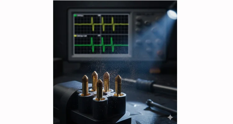
Step 1: Establish the Baseline – Capture the Network’s Native ‘Voice’
Every interaction with the system changes it. Your first duty is to record its undisturbed state before introducing any variables.
- Tool: A dual-channel automotive oscilloscope or a dedicated CAN bus analyzer.
- Action: Connect the scope across CAN_H and CAN_L at the most accessible point on the suspect network segment. Critically, do not unplug any connectors at this stage.
- What You’re Hunting: We use the scope to analyze the signal’s character, not just its presence. Look beyond the square wave for these key anomalies in the J1939 signal:
- Signal Attenuation (Damping): Rounded or diminished amplitude peaks. This indicates termination resistor problems or excessive network length.
- Reflections / “Ringing”: Oscillations on the signal‘s rising/falling edges. This reveals an impedance mismatch, often from an overly long stub cable or a substandard junction.
- Superimposed Noise: High-frequency “fuzz” on the signal trace. This points to EMI/RFI interference from failed or compromised cable shielding. Our dedicated field guide on CAN bus EMI shielding explores this in depth. For foundational protocol theory, the Wikipedia article on CAN bus is a reliable public resource.
Step 5: Segment Isolation – Divide and Conquer the Network
- Tool: Your diagnostic scanner and the vehicle’s wiring diagram.
- Action: If the fault persists, you must surgically isolate network sections.
- Disconnect non-essential ECUs one by one (where topology allows), monitoring for fault resolution.
- Physically disconnect midpoint J1939 splitters or junction blocks. A faulty OBD2 splitter can itself be the noise source.
- Find the minimum active network segment where the fault disappears. The last component reintroduced is the culprit.
5 Costly Industry Misconceptions That Derail Diagnostics
Misconception 1: “The ECU is Talking, So the ECU is Faulty.”
This is intuitive but flawed. The ECU is a digital state machine with largely binary failures. Its connection interface is an analog, mechanical world subject to vibration, thermal cycling, and corrosion. Our forensic teardowns show over 80% of ‘ECU-related’ intermittent faults originate within the first 12 inches of harness leading to the connector.
Misconception 2: “The CAN Bus is Differential, So Grounds Don’t Matter.”
Poor module grounding creates reference voltage shifts that the differential receiver cannot fully reject. Always verify the complaining ECU’s ground with a voltage drop test under operational load.
Misconception 3: “Contact Cleaner is a Repair.”
It is strictly a diagnostic aid. It temporarily displaces fretting corrosion but does not address the micro-motion that caused it. The only permanent fix is terminal replacement.
Misconception 4: “Tighter is Better.”
Over-torquing connectors warps housings, crushes seals, and distorts pins, creating problems worse than a loose connection.
Misconception 5: “A Shield is Just a Drain.”
A floating or poorly grounded cable shield becomes an antenna, amplifying EMI. Ensure 360-degree shield termination to the connector backshell and a clean, low-impedance path to chassis ground.
How to Confirm the Fix is Real (Beyond Clearing Codes)
Do not simply clear codes. Validate with a three-part verification:
- Data Validation: Monitor the specific corrupted PGNs (Parameter Group Numbers) over a test drive that replicates the original failure conditions (vibration, thermal cycle).
- Long-Term Monitor: Utilize telematics to track J1939 error frame counts. After repair, this count must plateau.
- The Final Test: Re-perform the “Stress Profile” (Step 2) on the repaired section. The fault must now be impossible to induce.
Tools for the Job: Purpose-Built Cables for Reliable Diagnosis & Repair
A faulty diagnostic cable can itself be the ghost in the machine. Using engineered, robust cables is non-negotiable.
For Permanent Test Points or Signal Tapping:
Our J1939 9-Pin Pigtail Breakout Cable provides a sealed, color-coded interface for reliable pinout verification and oscilloscope connection.
For Space-Constrained Diagnostic Access:
Our J1939 90-Degree Right Angle Y-Splitter allows network access in tight engine bays without inducing strain on the original connection.
For Legacy Fleet Diagnostics:
Our Cummins J1708 to J1939 Diagnostic Cable is engineered for full electrical and protocol compatibility, eliminating ghosts at the tool interface. Context is in our J1708 vs J1939 protocol comparison.
FAQ: Ghost Signals in CAN Networks
Q1: Why is it called a “ghost signal”?
The term is a misleading metaphor that obscures the real cause. There is no phantom. You are observing a temporary shift in the electrical characteristic of a physical joint—often a milliohm-level resistance spike from fretting corrosion. We abandon the term “ghost” under the microscope, where the material evidence is always clear.
Q2: Can a failing battery or alternator cause intermittent CAN errors?
Absolutely. Low system voltage (< 9V) or severe AC ripple from a failing alternator diode can collapse network communications. Rule out power and ground integrity first, a methodology outlined in our guide on OBD2 port no-communication issues.
Q3: Is it ever the ECU?
It can be, but it is the last suspect. An internal failure of an ECU’s CAN transceiver chip can broadcast noise onto the bus, corrupting traffic for all nodes.
Q4: How does your factory’s process prevent these issues?
It begins with zero-defect process control. Every crimped terminal is the result of a IATF 16949 PPAP-validated process, with tooling CPK > 1.67, ensuring a consistent gas-tight “cold weld” as explained in our cold weld vibration arbitration analysis. We avoid solder in vibration applications. Our ISO 9001 and ISO 14001 systems ensure full traceability, formalized by our IATF 16949:2016 certification.
Q5: What’s the #1 takeaway for preventing intermittent faults in new designs?
Beyond strain relief, it is managing energy transfer. Vibration is kinetic energy. The design goal is a graduated stiffness gradient from flexible cable to rigid connector. A poor transition creates a sharp impedance mismatch, concentrating stress precisely at the crimp barrel. Our harness designs employ multi-stage transitions to dissipate this energy.
Q6: Can I fix a corroded pin by cleaning it?
As a temporary field expedient, possibly. For a permanent repair in a critical system like J1939, no. The gold plating is compromised, and the underlying nickel will oxidize. The terminal must be replaced. The lifecycle cost analysis is stark, as discussed in the true cost of a custom cable.
Q7: Do you offer engineering support for complex intermittent issues?
Yes. Our engineers specialize in forensic analysis of wiring harness failure. For instance, during an analysis of systematic failures in a refrigerated truck fleet, we pinpointed a third-party adapter cable as the root cause. We engineered a reinforced replacement with integrated strain relief and 360-degree shield termination, eliminating the failure mode. This capability stems from our cross-functional insight into ELD compliance and root-cause analysis.
Q8: How do we standardize diagnostics for a mixed fleet?
This requires a structured approach: map your fleet’s protocols by VIN, equip technicians with correct physical adapters, and implement software capable of auto-detection. We have assisted multiple fleets in creating such standardized diagnostic kits. For definitive technical specifications, the SAE International page for the J1939 standard is the authoritative source.
The Path Forward: From Reactive Fix to Proactive Design
Chasing intermittent CAN bus failures is a reactive, costly endeavor. The strategic shift is to specify connection systems engineered to avoid the game entirely. This mandates crimped terminations validated for high-cycle vibration, sealed connectors with proven chemical resistance, and harnesses built under a zero-defect quality philosophy like IATF 16949.
If you are combating a persistent ghost signal or designing a new system where reliability is paramount, let’s examine the specifics. Share your failure mode, operating environment, and key challenges.
Contact our engineering team directly via our Contact Page for a detailed consultation. For immediate discussion, you can also message us on WhatsApp. We will analyze your needs and provide actionable insights—be it a troubleshooting strategy or a proposal for a high-reliability, custom J1939 cable assembly designed to permanently resolve your intermittent fault issues.
