

Most online “OBD2 adapter guides” just list specifications. They don’t teach you how to think like an engineer and match the interface to the job. This article provides the exact 5-step decision framework our factory uses internally to specify reliable diagnostic pathways, ensuring signal integrity from the first connection. For professionals, this framework is the difference between predictable success and costly downtime.
Where the Wrong Adapter Costs You Time and Money
This isn’t a hypothetical concern. The wrong adapter manifests in specific, expensive failures:
The Phantom Disconnect: Your scanner links, then drops mid-scan. You’re left diagnosing a ghost in the machine—vehicle, tool, or the adapter itself.
The Protocol Dead End: “Protocol Not Supported” halts the crucial ECU handshake before diagnostics even begin, turning a repair into a missed opportunity.
The Bricking Event: A weak or noisy signal during ECU flashing can corrupt the module’s firmware, transforming a simple repair into a major, costly replacement.
Port Destruction: Ill-fitting, cheap connectors can crack or damage the delicate pins of a J1962 port, adding a completely new and avoidable repair job.
The Root Cause: It’s More Than Just a Connector
The fundamental error is treating adapters as passive wires. A true professional-grade OBD2 adapter is an active extension of the vehicle’s diagnostic bus. Maintaining signal fidelity over distance, translating protocols correctly, and managing electrical load are hard engineering requirements. An adapter that works on a 2010 car will likely fail on a modern vehicle with switched CAN networks or a heavy-duty truck using the different physical and data layers of SAE J1939.
Protocol vs. Physical Connector
| Connector Type | Primary Application | Key Protocols Required | Critical Consideration |
| J1962 (OBD2) | Light-Duty (Cars/SUVs) | ISO 15765-4 (CAN), KWP2000 | Pinout accuracy is non-negotiable |
| Deutsch 9-Pin | Heavy-Duty Trucks | SAE J1939, SAE J1708 | Type 1 (Round) vs. Type 2 (Square) is a physical lockout. |
| Proprietary Connectors | Older European/Asian Cars | K-Line, D-CAN | Requires exact, vehicle-specific pinouts for deep access. |
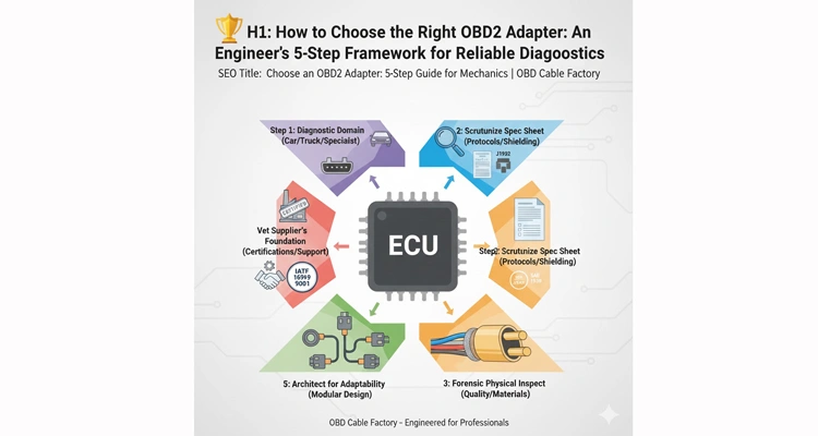
OBD2 Adapter Selection: The 5-Step Engineer’s Framework
Forget guesswork. Follow this deterministic process, distilled from our engineering team’s work with professional clients.
Step 1: J1939 and Diagnostic Tool Compatibility
Your most frequent jobs dictate the foundational tool.
- Light-Duty Shop (Cars/SUVs): You need broad protocol support. A high-quality, fully shielded universal cable is the base of your toolkit.
- Heavy-Duty & Commercial (J1939/J1708): This is a different world. A dedicated J1939 adapter is mandatory. First, visually confirm the connector: round Deutsch 9-pin (Type 1) or square (Type 2)? They are not interchangeable. For the actual connection, having the right breakout cable is critical. A reliable J1939 9-Pin Pigtail Breakout Cable provides the necessary interface for custom wiring. When your project requires connecting J1939 data to devices with a DB15 port, refer to our dedicated Complete Guide to Connecting J1939 9-Pin Data to DB15 Devices for step-by-step instructions.
- Brand-Specialist (e.g., BMW, Mercedes): Older or complex models require specific interfaces (e.g., K-line for flashing). Here, a dedicated brand cable is not a luxury, but a necessity for full access. Read our BMW OBD Protocol Guide for detailed protocol information.
- Fleet Telematics: Requires rugged, low-profile, and overmolded OBD2 cables engineered to withstand constant vibration and temperature cycling without dislodging.
Step 2: Deconstruct the Specification Sheet Like an Auditor
Don’t just read the specs—challenge them against your needs from Step 1.
| Specification | What to Demand | Why It’s a Signal Integrity Gatekeeper |
| Supported Protocols | Must explicitly list the vehicle’s standard (e.g., SAE J1939 for trucks, ISO 15765-4 for modern cars). | A missing protocol is a guaranteed communication failure. |
| Connector Types | OBD2 (Female), DB9, USB, and the correct Deutsch (Type 1 or 2). | Defines the physical reality of your connection. |
| Cable Shielding | “Dual-shielded (foil + braid) with a drain wire” is the professional minimum. | This is your defense against shop EMI/RFI that corrupts data, especially during programming. |
| Pinout Integrity | Verified, pin-to-pin mapping, critical for K-Line and J1939 variants. | On a J1939 bus, one miswired pin can silence an entire vehicle subsystem, not just cause a “no comm” error. |
As an OEM/ODM factory, we don’t just supply cables; we supply certified data pathways.
💡 Technical Deep Dive: Understanding the underlying protocols is foundational to making the right choice. For an authoritative reference on the CAN bus technology that forms the basis for many modern standards (including J1939 and ISO 15765-4), the CAN Knowledge Base maintained by CAN in Automation (CiA) is an invaluable professional resource.
Step 3: Execute a Forensic Physical Inspection
Judge build quality with an engineer’s eye:
- Overmold & Strain Relief: Look for a seamless, single-shot overmold. True IATF-compliant overmolding shows uniform flow and zero gap between cable and connector—defects our 100% visual inspection catches. Anything less invites fatigue failure.
- Pin Finish: We specify 15µin gold plating because it’s the verified minimum to survive our 48-hour salt spray test, simulating years of under-hood corrosion that degrades nickel-plated connections.
- Cable Jacket: Must be flexible (e.g., PUR) yet chemically resistant, rated for your shop’s temperature extremes.
- The Manufacturing Standard: Our adherence to IATF 16949:2016 means every solder joint and crimp is treated as a safety-critical automotive component.Learn more about our IATF 16949:2016 Certification here.
Step 4: Architect for Adaptability
- The Modular Mindset: The most efficient long-term strategy is a robust base cable with interchangeable vehicle-side connectors (Type 1, Type 2, etc.). This future-proofs your core investment.
- The OEM/ODM Edge: This modularity is where partnering with a direct manufacturer is critical. We can build this system to your exact workflow, with custom lengths, color-coding, and labeling.
Step 5: Vet the Supplier’s Engineering Foundation
The product is only as good as the support behind it.
- Certification as Proof: Demand proof of ISO 9001 and IATF 16949. These are not just certificates; they are documented systems for quality and defect prevention. Similarly, for heavy-duty applications, ensuring your adapter complies with the official SAE J1939 Standards is non-negotiable for reliable communication.
- Testing Protocol: Every unit must pass a 100% electrical continuity and isolation test—no batch sampling. This eliminates the risk of a single faulty unit reaching you.
- Engineering Dialogue: Can they review your pinout diagram and confirm compatibility? Our team does this to prevent mismatches before an order is placed.
5 Critical Pitfalls to Sidestep
- Myth 1: The OBD2 Port is a Universal Standard. Reality: It’s Just a Doorway—What’s Behind It (CAN, J1939, K-Line) Determines Your Key.
- The False Economy: Why “Saving” $50 on a Cable Can Lead to a $5,000 ECU Replacement
- The J1939 Type Mismatch: Ordering a Type 1 (round) for a Type 2 (square) port is a physical impossibility and a hard operational stop.
- The Signal Attenuation Trap: Using long, unshielded cables guarantees signal degradation and intermittent faults. Length demands superior shielding and proper wire gauge.
- Supplier Certification Blind Spot: Buying from an uncertified source means gambling on undocumented material quality and process control. (External Link: What is PPAP?)
How to Know You’ve Made the Right Choice
Validation comes from performance:
- Consistent First-Link Success: Your tool establishes a stable connection on the first attempt, across different vehicles.
- Uncorrupted Data Flow: Live data streams and long logs are free from dropouts or phantom “ghost” codes.
- Flawless Critical Operations: High-stakes tasks like module coding and programming complete without error—the ultimate test of signal integrity.
- Enduring Physical Build: The connector feels secure, and the cable shows no signs of wear or fatigue after months of daily use.
Matching the Solution to Your Diagnostic Challenge
| Challenge/Application | Our Engineered Solution | Core Design Focus |
| Heavy-Duty Trucks (J1939/J1708) | J1939 Adapter Series | Precise Deutsch Pinout, Vibration-Resistant Construction |
| General Diagnostics (Cars/SUVs) | Professional OBD2 Cable Series | IATF-Compliant Materials, Dual-Layer Shielding |
| Fleet Tracking / Telematics | Low-Profile / Angled OBD2 Cables | Secure Latch Mechanism, Minimal Disruption |
| Unique Tools or Integration Needs | OEM/ODM Engineering Service | Full Customization: Lengths, Pinouts, Connectors |
Frequently Asked Questions (FAQ)
Q1: What’s the single biggest difference between a cheap adapter and a professional-grade one?
A: Predictable Signal Integrity. The cheap one might work intermittently; the professional one, built to IATF 16949 standards, delivers a clean, stable signal every time—under load, over distance, and in electrically noisy environments.
Q2: Can I damage my car’s ECU with the wrong OBD2 adapter?
A: While unlikely during a simple scan, an unstable connection or transient voltage spike from a poorly-made adapter during ECU programming can corrupt the firmware, often requiring a full ECU replacement.
Q3: My J1939 adapter won’t fit. How do I know if I need Type 1 or Type 2?
A: This is critical. Type 1 has a round Deutsch connector housing. Type 2 has a distinct square housing. They are physically and electrically incompatible.
Q4: Do I need a different adapter for CAN FD (Flexible Data-Rate) vehicles
A: Yes. CAN FD operates at significantly higher data rates. The adapter’s internal wiring and shielding must be explicitly designed to handle these speeds without introducing bit errors.
Q5: How important is cable shielding for general diagnosis?
A: Essential. Shop environments are electrically noisy. Proper shielding is your primary defense against electromagnetic interference (EMI), which is the leading cause of intermittent, hard-to-diagnose communication glitches.
Q6: What does “100% tested” mean in your factory context?
A: It means every single cable, without exception, passes through an automated test station that verifies correct pin-to-pin continuity, checks for any short circuits or open wires, and validates basic signal integrity before packaging.
Q7: Can you make an adapter with a custom connector on the tool end (e.g., to fit an older, proprietary scanner)?
A: Absolutely. This is a core function of our OEM/ODM service. We regularly engineer cables that interface J1962/J1939 to legacy or proprietary connectors like DB9, DB15, or custom USB formats.
Q8: What certifications should I prioritize when vetting a supplier?
A: IATF 16949 is the non-negotiable gold standard for the automotive supply chain. It demonstrates a systemic, prevention-focused approach to quality that goes far beyond the basic quality assurance of ISO 9001.
Professional Engineering Support & Customization
You now possess the five-step engineering framework to specify reliable diagnostic connections. Choosing the right adapter is an investment in your shop’s operational certainty.
If your challenge involves mixed fleets, legacy tool interfaces, or custom telematics integration—this is where our engineering partnership delivers the greatest value. Submit your most complex pinout diagram for a complimentary compatibility audit.
For immediate technical consultation and real-time support.
Submit detailed specifications for formal quotation and project review.
We are your engineering partner for reliable OEM customization, backed by 20 years of focused expertise and IATF 16949-certified quality assurance
