

You’re sitting in a $500,000 excavator. The engine’s running. Your laptop is connected. And the diagnostic software just stares back at you: “Link Error.”
Before you call the dealer or swap the ECU, let me show you what 20 years of building these cables on our factory floor has taught me about where the real problem hides.
In about 60% of the cases I’ve consulted on across mines and job sites, the problem isn’t the brain of the machine—it’s the nervous system. Specifically, the tiny metal terminals inside that 9-pin Deutsch connector that someone assumed was “good enough.” If you’ve ever dealt with intermittent issues that seem to disappear when you wiggle the cable, you know exactly what I’m talking about. For a deeper look at how misdiagnosing these connector problems leads to unnecessary downtime, see our analysis on J1939 Type 1 vs Type 2 misdiagnosis costs .
This guide isn’t about reading generic fault codes. This is about verifying the very foundation of communication: pinout integrity, voltage supply under load, and the actual signal waveform that tells you whether the copper is telling the truth. We’ll look at the data, not just the light on the dash.
The Usual Suspects: Where Field Communication Dies
I was on a site outside Elko, Nevada a few years back—high desert, lots of dust, big temperature swings. A fleet of haul trucks was throwing intermittent communication errors that had everyone stumped. The local techs had swapped three ECUs and a wiring harness—costing thousands—before I arrived.
I asked the senior tech one question: “Show me how you test the connector.”
He grabbed his multimeter, touched the inside of the pins (we’ll talk about why that’s a mistake later), and said, “Grounds good, power good.”
He was right about the DC voltage. But the problem wasn’t the DC. It was the signal.
Before we dive into the fix, let’s look at where these failures typically hide:
- The High-Vibration Environment: Right next to the engine block or transmission housing. Vibration doesn’t just shake things loose—it work-hardens copper until it snaps like a paperclip. I’ve pulled apart connectors that looked fine but had hairline fractures at the crimp. For a detailed look at how vibration destroys connections, read our piece on cold weld vibration arbitration .
- The Corrosion Zone: Exposed to pressure washing and road salt. That green fuzz inside the connector isn’t just ugly; it’s a rectifier. It turns clean digital signals into noise that confuses the CAN transceiver.
- The “Mechanic’s Hook” Point: Where someone before you back-probed the wires and stretched the insulation, letting moisture wick inside. The outside looks fine. The inside is a swamp. We see this constantly on heavy-duty equipment that’s been in the field for years.
The Physics of Failure (Why Ohm’s Law Isn’t Enough)
To fix it permanently, you have to understand what’s happening electronically. A static resistance reading won’t catch what happens when the data rate hits 250kbps. Understanding how to diagnose intermittent CAN bus failures requires looking beyond simple continuity checks.
The Pinout (SAE J1708 / J1939)
First, let’s get our bearings. On a standard 9-pin Deutsch diagnostic connector (DT series, common in heavy-duty trucks and off-highway equipment), here is the full engineering pinout reference. We care about all of these, but the first five are where 90% of the failures live. This connector is defined within the broader SAE J1939 standard , which governs communication across commercial vehicle networks . For a more detailed comparison of connector types, see our J1939 Type 1 vs Type 2 guide .
| Pin | Function (Common Usage) | Typical Voltage (Ignition On) | What I’ve Learned the Hard Way |
| A | Ground (Battery Negative) | 0 V (Reference) | Pin A is where the current comes home. I’ve seen perfectly good ECUs throw “communication lost” errors simply because this pin had a 0.4V offset from true chassis ground. That’s not “floating voltage” in theory—that’s a 500-ton truck that won’t move. |
| B | Battery Positive | 12V / 24V (Raw battery) | Powers the diagnostic adapter. If this dips below about 9V on a 12V system, the adapter browns out and resets mid-conversation. |
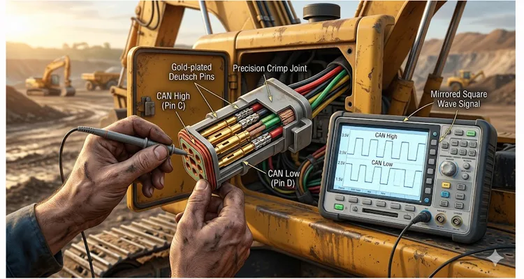
| C | CAN High (J1939 Primary) | ~2.5 V (Idle) | Carries the data signal. When the network talks, this one jumps to about 3.5V. |
| D | CAN Low (J1939 Primary) | ~2.5 V (Idle) | The partner to C. When C jumps up, D drops to about 1.5V. Like a seesaw. |
| E | J1708 Data Link (+)/ Shield | Varies / 0V | Older network, or sometimes shield drain. Honestly? I rarely see these used anymore on post-2010 equipment, but the pin is there. |
| F | Ignition (Key Switch) | 0V (Off) / 12-24V (On) | Wakes up the diagnostic adapter. If this is dead, the adapter never turns on. |
| G | CAN High (Secondary Bus) | ~2.5 V (Idle) | For auxiliary ECUs (ABS, Body Controller). When the main bus works but ABS won’t talk, check here. |
| H | CAN Low (Secondary Bus) | ~2.5 V (Idle) | Differential pair for secondary bus. |
| J | OEM-Specific / Proprietary | Varies | Usually for dealer-level tools only. Leave it alone. |
The “Dirty Power” Trap
We always check for voltage between A and B. That’s step one. But here’s where the multimeter lies to you.
I watched a tech spend four hours chasing a “bad ECM” last month. At key-on, he had 25.5V on pin B. Perfect, right? But during cranking, that voltage didn’t just sag—it collapsed to 11V for about 300 milliseconds. His meter averaged it out. The adapter didn’t. It reset mid-handshake.
The diagnostic session started, then died. Over and over. That’s a classic voltage drop symptom that a static test misses completely.
The Signal Integrity Blind Spot
Pins C and D (the primary CAN data lines) are where the real conversation happens. On a J1939 network, these lines need to be a perfect differential pair. At idle, they should sit at about 2.5V each.
Watch the screen when you hit “connect.” If the network is healthy, pin C should jump to about 3.5V while pin D ducks to 1.5V—like a seesaw. If that seesaw is sluggish or uneven, don’t blame the software yet. The copper isn’t carrying the conversation.
If corrosion adds resistance to Pin C, that “idle” reference moves. The ECU might still talk, but the adapter hears static. This is where oscilloscope waveforms become your best friend. For a comprehensive guide on dealing with electrical noise, check out our field guide to CAN bus EMI shielding .
How We Actually Test This (Step-by-Step, No Fluff)
Let’s go through my diagnostic routine. I’m assuming you have a multimeter and, ideally, an oscilloscope (even a cheap handheld one beats guessing). The physical layer principles we’re applying here—like proper CAN bus termination—are detailed in resources like this technical overview of CAN physical layer issues .
Step 1: The Visual Check (The 5-Second Clue)
Look at the plastic around the pins. If the plastic is melted or deformed, someone back-fed 110V AC into the system or welded with the diagnostic port connected. That’s a dead ECU. Walk away.
Look at the receptacles (the female pins). They should have a consistent round shape. If they’re spread open like a flower, they won’t grip the adapter pins. This is the #1 mechanical failure I see. Someone used a probe that was too thick, stretched the metal, and now the connection is intermittent.
Step 2: Load-Testing the Power (A&B)
Grab your multimeter. Set it to DC Volts. Measure between Pin A and Pin B.
- 12V System: Should read 11.0V to 13.5V (with key on).
- 24V System: Should read 22.0V to 27.0V (with key on).
Now, here is the trick the old manuals don’t tell you: Load test it.
Take a headlight bulb (or a 10-ohm resistor) and carefully bridge it between Pin A and Pin B for just a second while watching the voltage. If the voltage crashes to zero, you have a high resistance connection or a bad ground. The wire looks fine from the outside, but the crimp inside the connector is corroded. The wire is lying to you.
Step 3: The Pin-Drag Test (Mechanical Integrity)
This is a “feel” test. Turn the key off.
Take your mating adapter plug. Insert it. Remove it.
It should have a firm, noticeable drag. If it slides in like a hot knife through butter, the female terminals inside the machine’s connector are fatigued. They’ve lost their grip.
The Fix: You can use a small pick to gently bend the female terminal tangs inward to restore tension. Do this carefully; break one off, and you’re repinning the whole connector. I’ve done it. It’s not fun.
Step 4: Looking at the “Conversation” (C&D with a Scope)
This is where you separate yourself from the average mechanic. Using a J1939 9-pin pigtail breakout cable makes these connections much easier and prevents damaging the vehicle’s connector.
- Connect your oscilloscope ground to Pin A.
- Put Channel 1 on Pin C (CAN High) .
- Put Channel 2 on Pin D (CAN Low) .
- Turn the key on.
You should see two flat lines, roughly 2.5V each.
Now, try to initiate communication. Click “Connect” on your software.
You should instantly see two mirrored square waves. When Pin C goes up to ~3.5V, Pin D should drop to ~1.5V.
- If the signal is there but noisy (lots of sharp spikes): You have ignition noise. Bad spark plug wires, a failing alternator, or poor shielding. Check the harness shielding. Our guide on CAN bus shielding and filtering covers how to address this.
- If the signal is rounded off (looks like a sine wave): You have too much capacitance or resistance on the line. This is almost always corrosion or water in the connector. The signal can’t switch fast enough.
- If the signal is distorted or looks like a staircase: You have a reflection. The signal is bouncing. Check your network terminators. With the power off, measure resistance between Pin C and Pin D. You should see about 60 ohms (two 120-ohm resistors in parallel). If you see 120 ohms, you’re missing one terminator. If you see near zero, you have a short.
- If there is no signal at all: Check continuity between Pin C and the ECU pin. A resistance check of less than 10 ohms is the target. If it’s higher, you have a broken wire or a bad crimp somewhere in between.
The “I Thought I Fixed It” Mistakes (5 Common Errors)
I’ve made every single one of these. Learn from my pain.
- Probing the Wire, Not the Pin. You back-probe the wire and get a perfect reading. But when you plug the adapter in, the pin spreads open inside the housing and loses contact. You tested the wire, not the connector. Always test from the front (pin-to-pin) if possible.
- Ignoring the Adapter Cable. I spent three hours troubleshooting a $100k machine once. It was a broken wire inside my own $20 dongle. Your tools are part of the system. Test them. If you’re using a cheap cable, borrow a known-good one before you chase ghosts. We’ve built enough custom diagnostic cables to know that the cheap ones fail first. A reliable option like the Cummins J1708 to J1939 diagnostic cable ensures you’re not fighting your own equipment. For fleet managers, we’ve outlined the real cost of these failures in our diagnostic downtime cost calculator guide .
- Assuming “Ground is Ground.” In a 24V system, the return path matters. If Pin A has a 1V offset from chassis ground due to a bad engine bond strap, your data signals get skewed. Check resistance between Pin A and a known good chassis bolt. It should be near zero. Not 0.5 ohms. Near zero.
- The “Tapping” Fix. Tapping the connector while trying to connect. If wiggling it makes it work, you have a mechanical retention failure. Stop wiggling and fix the terminals. Wiggling just hammers the pins wider and makes it worse.
- Forgetting the Terminator. As mentioned above, if your square waves look like a staircase, you have a reflection problem. Don’t assume the terminators are there. Check for those missing 120-ohm resistors.
How to Know You Actually Fixed It
You hit “Connect” and it works. High fives all around. But don’t pack up your tools yet.
Run the engine up to operating temperature. Hit the horn, turn on the AC, cycle the lights—load the electrical system. Now watch your saved waveform. Is it still clean?
I keep a folder on my laptop called “Known Good.” When a truck comes in next month with a weird glitch, I pull up that file. If the waveform doesn’t match, I know where to start digging. That’s the value of waveform capture.
The “Shake” Test
With the engine running and the scope attached, vigorously shake the harness. Not gently—wiggle it like you mean it. The waveform on the screen should be rock solid. If it glitches, you still have a frayed wire inside the insulation. Keep digging. This is how we validate harness integrity before a custom cable leaves our shop.
Spec’ing the Right Hardware for the Next Job
Sometimes, the OEM connector is just poorly designed for the environment. When we work with clients at our facility—whether it’s a custom harness for a prototype ag vehicle or a heavy-duty extension cable—we focus on the physical layer that software guys forget about. For agricultural applications specifically, our J1939 cable agriculture survival guide covers the unique challenges of that environment.
The right connector starts with the right metallurgy and sealing. If you are designing a system that has to survive a salt spray test, you can’t just buy any off-the-shelf plug. You need to look at the plating (tin vs. gold) and the ingress protection (IP rating). Gold costs more, but in a wet environment, it pays for itself. We’ve seen gold-plated terminals outlast tin by years in coastal operations.
We’ve built custom harnesses where the customer requested a specific wire gauge (AWG) because they had a 50-foot run between the cab and the ECU. Standard 18 AWG wouldn’t carry the voltage without drop. We had to bump it to 14 AWG. The voltage drop disappeared.
If you are looking for a reliable connection for your test bench or need to replace a faulty vehicle harness, don’t just grab the cheapest cable. Look for the manufacturing markers: 100% tested, RoHS compliant materials, and a factory that follows ISO 9001 or IATF 16949 standards. You can view our IATF 16949:2016 certification and our ISO 14001:2015 certification online. For a deeper look at what zero-defect manufacturing means, see our piece on the IATF 16949 PPAP zero-defect cable process .
In our own shop, we run a 5S-managed, climate-controlled assembly floor specifically to keep humidity out of the crimping process—because humidity leads to the “mystery” corrosion we talked about earlier. We’ve been building these for over 20 years; we know where the weak points are because we’ve seen them all fail.
Frequently Asked Questions from the Shop Floor
Q: I’m good with a soldering iron—can’t I just solder the pins?
A: You can, and I have. But I’ve also pulled those same connectors out of a dump truck six months later to find the wire snapped right at the solder joint. Vibration doesn’t care about your iron skills. A proper crimp lets the wire breathe and flex. If you’re prototyping on a bench? Solder away. If this machine has to move—crimp it. That’s why we use precision crimping on every cable we ship. For a detailed technical comparison, read our guide on crimp vs. solder vibration reliability .
Q: Why do I have 5V on Pin A when the battery is 24V?
A: You have a massive voltage drop. You are likely measuring through a path of corrosion or a nearly severed wire. Stop testing and start inspecting the harness for physical damage. Look for green fuzz, bent pins, or melted insulation. This is a classic high resistance connection symptom.
Q: What is the difference between J1708 and J1939 on this connector?
A: Physically, they often share the same pins (D&E for old J1708, C&D for J1939). J1708 is slower (baud rate) and uses a single-ended signal. J1939 is faster and uses a differential signal (CAN) . Many modern ECUs broadcast both on the same pins, but if your pins C and D are dead, J1939 won’t work. If you’re working on pre-2005 equipment, you might still need J1708.
Q: How tight should the pins be?
A: The retention force should be firm. If you can hold the adapter plug vertically and the machine connector supports its weight without falling, it’s probably okay. If it falls under its own weight, the pins are loose. If you have to fight to get it out, they’re too tight—or bent.
Q: Can water in the connector cause a short?
A: Water alone isn’t conductive enough to short 24V, but dirty water (salt/grime) is. More importantly, water changes the dielectric properties of the air, causing signal reflection and attenuation—that rounding off of the square waves we talked about. Even if it doesn’t short, it kills communication. That’s why IP-rated connectors matter.
Q: Do I really need an oscilloscope?
A: For basic “no comms,” no. A multimeter and a test light will find 80% of the problems. For intermittent issues—the ones that cost you hours of downtime—yes, a scope pays for itself on the first job. A cheap handheld scope is better than no scope. You need to see the waveform.
Q: Why does the factory recommend checking resistance between P1:23 and Pin C?
A: They are checking for a clean, low-resistance path from the ECU (P1:23) to the connector (Pin C). If that resistance is high, the wire is bad, or the crimp is failing. That number—10 ohms or less—is the threshold. Anything above that, and you’re losing signal. It’s a basic continuity check that catches a lot of bad crimps.
Q: I measured 60 ohms between C and D, but I still have no communication. What now?
A: Check the bias voltage. With the key on, you should see that 2.5V idle. If you have 0V or 5V, the transceiver in the ECU might be dead, or the wires are shorted to ground or power. If the bias is wrong, the network can’t establish a dominant state. You’ve confirmed the termination resistors are there, so now look at the transceiver. Electrical noise from sources like VFDs and industrial equipment can also cause bias issues.
Q: What voltage should I see on Pin C?
A: On a standard J1939 port, you should see 2.5V at idle. If you see 0V, the line is shorted to ground. If you see 5V, it’s shorted to power. If you see something in between but unstable, you have a connection issue. That’s your CAN bus idle state.
Look, at the end of the day, a diagnostic connector is just a door. If the hinges are rusty or the frame is bent, it doesn’t matter if you have the key. We’ve been building these “doors” and the cables that go through them for over two decades. We’ve seen every way a connection can fail, usually because someone saved two cents on a crimp terminal.
If you are working on a project where you can’t afford those two-cent failures—whether it’s a custom-length tester cable or a full vehicle harness overhaul—I’d be happy to talk through the specs. We handle OEM customizations from length and color to specific AWG requirements. For a deeper understanding of what goes into a truly durable cable, read about our J1939 ArmorLink vibration-validated cable assemblies .
You can reach our engineering support team through the Contact Page , or if you want to discuss a specific application immediately, ping us on WhatsApp .
No pressure. Just good talk about good connections.
