

Last Tuesday, I watched a senior technician spend three hours chasing a no-comm code on a 2022 Peterbilt. He swapped cables, rebooted laptops, even pulled the ECU fuse. Finally, I walked over, looked at the Deutsch connector, and said, “Pin C is pushed back.” Thirty seconds with a pick tool and the truck was talking. That moment—when the obvious hides in plain sight—is why I’m writing this.
Here’s the thing about that Deutsch HD10 or HD16 connector – it looks simple. Nine pins, rugged housing, IP67 rating. But inside those nine pins lives a communication handshake that’s more temperamental than a 30‑year‑old VOCON system. The plastic feels solid. The click is satisfying. None of that matters if the termination resistors are missing.
Let me walk you through the real‑world issues, the fixes, and why this little circular connector causes more downtime than failed turbos in some fleets. We’ve been manufacturing these assemblies for over 20 years in an IATF 16949 certified facility, and I can tell you that 90% of the “ECU communication failed” calls we get trace back to this connector.
The Three Times You’ll Curse This Connector
1. The Fleet Integration Nightmare
You just bought 12 used Kenworth T680s from an auction. They’re all 2018‑2020 models. You’re installing your standard ELD gateways, and three of them won’t communicate. Two more show data but drop off randomly. The last one is fine. Same model year, same engine, same connector – different results. Now your compliance manager is sending hourly emails with escalating red font, and the safety audit is three weeks away. I’ve walked into fleets where they’d already ordered replacement ECUs before anyone thought to check the Deutsch connector pinout. If you’ve ever dealt with ELD compliance audit failures, you know exactly how this feels.
2. The Field Service Breakdown
You’re 200 miles from the shop on a roadside diagnostic. Customer’s truck derated. You connect your laptop to the J1939 adapter, and Device Manager shows the COM port fine, but the software says “No Vehicle Communication.” You check fuses. You check voltage. You’re sweating because the asphalt is softening your boot soles, and the reefer unit next to you is idling at 180 decibels. I’ve been that guy. The problem was never the truck—it was the 9‑pin diagnostic connector wiring.
3. The Custom Build That Won’t Wake Up
You’re building a custom vehicle – maybe a school bus conversion, maybe a specialty ag sprayer. You’ve installed a third‑party display or a VCU. Everything is wired per the pinout diagrams you found online. But the modules aren’t talking. The CAN network is silent except for the noise of your own confusion. We get calls like this weekly at the factory. Nine times out of ten, the Deutsch pinout was copied from the wrong source.
Why the Connector Lies to You (The Technical Root Cause)
The 9‑pin Deutsch connector – technically the Deutsch HD10 series – isn’t just a power plug. It’s a three‑protocol interface hiding in one shell. And that’s where the trouble starts.
Here’s the design compromise that haunts us: SAE wanted one connector that could talk to a 1985 Detroit Diesel and a 2024 Cummins X15. So they stacked J1708—a protocol slow enough to watch individual bits travel—next to J1939 CAN, which screams data at 250,000 bits per second. They put different speeds on the same physical pins, then trusted technicians to never mix them up. Twenty years later, I’m still untangling that decision in service bays. The official SAE J1939/13 standard defines this connector and its pin assignments for diagnostic purposes.
Here’s what’s actually happening on those pins:
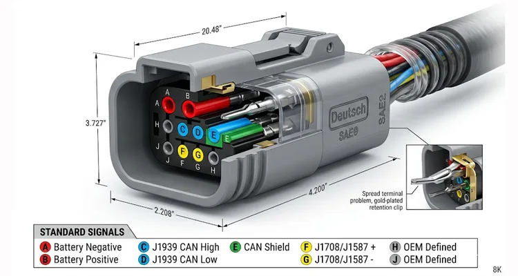
| Pin | Standard Signal | What It Really Does | Common Pitfall | Field Note (What I’ve Actually Seen) |
| A | Battery Negative (Ground) | Returns power for the scanner; reference for J1708 | Corrosion here kills everything | On a 2018 Western Star, corrosion on this pin caused the scanner to show transmission temp as -40°F. Took us two days to find it. |
| B | Battery Positive (+12V/+24V) | Powers your diagnostic tool | People assume it’s always hot | Freightliner Cascadias after 2017: this pin is ignition‑switched. Test with key on or you’ll chase ghosts. |
| C | J1939/CAN High | 2.5V nominal, 2.5‑3.5V active | Susceptible to shield shorts | Had a fleet of refuse trucks where Pin E was shorted to C internally—every truck lost comms when the packer cycled. |
| D | J1939/CAN Low | 2.5V nominal, 1.5‑2.5V active | Gets swapped with C constantly | Found a 2019 Mack Anthem last month where a previous repair swapped yellow and green. No communication for six months. |
| E | CAN Shield | Drains RFI to ground | Left floating, connected wrong | Saw a custom harness where shield was tied to ground at both ends. Created a ground loop that looked like a sine wave generator. |
| F | J1708/J1587 (+) | 0‑5V data line, 9600 baud | Obsolete but still expected | Many 2020+ trucks still broadcast critical data here. Ignore it and you’re blind to half the network. |
| G | J1708/J1587 (-) | Return for J1708 | Often tied to ground incorrectly | DIY repairs frequently jumper this to Pin A. Kills the differential signal. |
| H | OEM Defined | Whatever the truck maker wanted | Mystery function, leave alone | We once traced a no‑start condition to a Peterbilt using Pin H for a proprietary security interlock. |
| J | OEM Defined | Whatever the truck maker wanted | Mystery function, leave alone |
This table represents the standard Deutsch 9‑pin connector pinout for J1939 and J1708, but as the field notes show, theory and reality rarely align. Understanding the difference between J1939 Type 1 vs Type 2 connectors is crucial before you even pick up a multimeter.
The Step-by-Step Diagnostic Walkthrough (Not Theory – What Actually Works)
I’ve done this hundreds of times. Here’s the sequence that finds the problem 95% of the time without wasting hours.
Phase 1: The Visual (Don’t Skip This)
Put down the multimeter for 60 seconds.
Pull that Deutsch connector apart. Look at the pins – really look at them. The female terminals in the harness side are notorious for spreading open after years of plugging/unplugging. I’ve seen brand‑name diagnostic cables where pin C (CAN High) was pushed back so far it wasn’t making contact. We spec 0.76µm gold plating on our terminals—that’s 30 microinches for the old‑school guys. Cheap copies use 0.1µm flash gold that wears through in 50 insertion cycles. After that, you’re making intermittent contact through oxidation, which is worse than no contact at all. When you’re debugging a J1939 network, a spread terminal is invisible but deadly.
Check the color. If the connector body is green instead of the usual gray or black, that’s a Type 2 J1939 connector rated for 500kbps. Your older diagnostic tool might only speak 250kbps. The plug fits. The data won’t. We’ve documented numerous cases of J1939 Type 1/Type 2 misdiagnosis costing fleets serious downtime. We keep adapters in our shop for exactly this scenario.
Phase 2: Power Verification (The Obvious That Isn’t)
Set your meter to DC volts. Backprobe pins A and B.
- Key off: You should see battery voltage.
- Key on: Voltage should stay present.
Here’s the trap: On many vehicles – especially International and older Freightliner – pin B is ignition‑switched, not constant. If you’re testing with the key off, you’ll see zero volts and chase ghosts. If your diagnostic tool has an internal battery, it might power up from that, fooling you into thinking the connector has power when it doesn’t.
I had a 2019 Paccar MX‑13 last month. The customer had replaced three ECMs trying to fix a no‑comm issue. The problem? A blown 10‑amp fuse in the cab fuse panel labeled “CIG LTR” (cigarette lighter). That fuse powered pin B. Always verify the Deutsch connector power pins under load. If you’re dealing with a no‑communication situation at the OBD2 port, the same principles apply.
Phase 3: The 60-Ohm Test (J1939 Sanity Check)
This is non‑negotiable. With the key off, meter set to resistance, probes on pin C and pin D.
You want to see 55 to 65 ohms. Every cable we ship is tested on a network analyzer to verify this 60Ω match. It’s not just a continuity check; it’s signal integrity validation.
- 60‑65 ohms: Perfect. Both 120‑ohm termination resistors are present and healthy. Your J1939 network is properly terminated.
- 120 ohms: You’re only seeing one termination resistor. There’s an open somewhere in the backbone, or a module isn’t connected.
- Less than 10 ohms: Short between CAN High and CAN Low. Start looking for pinched wires.
- Infinite/OL: Complete open. Check the connector for broken wires first.
Real talk: I documented six 2023 Kenworth T680 service trucks from the same upfitter last year. All six showed 120 ohms at the diagnostic port. The upfitter had terminated the backbone at the chassis modules but forgot the dash connector. The dealer said “it’s fine” until the telematics units dropped off every time the AC clutch cycled. The 9‑pin Deutsch connector was physically fine, but the J1939 pinout was useless without proper termination. For those who need to tap into the network cleanly, we offer a J1939 9‑pin pigtail breakout cable that maintains signal integrity while providing access.
Phase 4: Voltage Bias (The Fingerprint Test)
Switch your meter to DC volts, key on.
- Pin C to ground: Should be 2.5 to 3.5V
- Pin D to ground: Should be 1.5 to 2.5V
Add them together. You should get roughly 5 volts.
If both pins read exactly 2.5V, that’s a red flag. It usually means the CAN transceivers are powered but there’s no network activity – like a dead node holding the bus in recessive state, or both wires shorted together. I’ve seen this on Cummins engines where a failed sensor took down the entire CAN bus.
If one pin reads 0V and the other reads 5V, you have a short to ground or power on one leg. This is almost always a wiring issue in the Deutsch connector harness.
Phase 5: J1708 Legacy Check
If J1939 looks good but you still can’t communicate, suspect the tool is defaulting to J1708. Some older diagnostic software tries J1708 first.
Check pins F and G:
- Key on, engine off: You should see fluctuating voltage between 0‑5V as data transmits.
- At idle: You’ll see chatter. If it’s flatline, J1708 is dead.
Many modern trucks still broadcast critical data on J1708 even if J1939 is present. According to the SAE J1708 standard, this protocol uses RS‑485 transceivers and is commonly implemented by American truck manufacturers and Volvo for transmitting fuel level and other critical data. If your tool expects it and it’s missing, communication fails. We’ve built custom diagnostic cables for fleets that needed both protocols active to read transmission data. For Cummins applications, we offer a dedicated Cummins J1708 to J1939 diagnostic cable that ensures full compatibility across engine families.
Six Mistakes I See More Often Than Blown Head Gaskets
1. Assuming All 9‑Pin Connectors Are Wired Alike
I learned this the hard way on a 2003 International 8600 with an ISM engine. The customer’s Pro‑Link couldn’t find any MIDs. Turned out that truck was wired for J1708 only—the factory never populated pins C and D. We spent two hours backprobing before we realized we were looking for CAN signals on a J1708‑only truck. The consequence? The fleet almost replaced a perfectly good ECM. The Deutsch connector pinout varies by year and manufacturer.
2. Ignoring the Shield (Pin E)
Pin E is supposed to be a drain wire for the CAN shield. It should connect to ground – but at one point only. I’ve seen harnesses where the shield was tied to battery ground at both ends, creating a ground loop that injected so much noise the CAN signal looked like a horror movie. In high‑EMI environments like refuse trucks or logging equipment, a poorly grounded Pin E makes the J1939 network unreadable. Getting the CAN bus shielding and filtering right is essential for reliable communication.
3. Reversing CAN High and Low
It sounds basic. It happens constantly. On a 2019 Mack Anthem last month, a previous repair had swapped the yellow and green wires at the bulkhead. The differential voltage canceled out completely—0 volts between C and D. The truck ran fine, but no diagnostic tool could talk to it. The driver had been living with a check engine light for six months because “the dealer couldn’t figure it out.” The 9‑pin Deutsch connector wiring was reversed, but the connector itself was fine.
4. Overlooking the “Ignition On” Requirement
On Cummins ISX15 CM2350 applications, pin B needs ignition voltage. I had a 2020 Peterbilt where the ignition switch failed internally—the truck started fine, but the accessory circuit didn’t energize. The scanner powered up from its internal battery, so the technician assumed the port was live. Three hours of CAN diagnostics later, someone thought to check voltage at pin B with the key on. Zero volts. New ignition switch. Problem solved in 20 minutes. The Deutsch connector power pin was dead, but the scanner’s internal battery hid the symptom.
5. Using the Wrong Connector Type
The market is flooded with cheap Deutsch “compatible” connectors. They look right. They click together. But the terminal retention is garbage. Pin spacing might be slightly off. After 50 temperature cycles from -40°F to 200°F, they develop micro‑cracks. Intermittent communication is worse than no communication – it’s a ghost in the machine. We’ve had customers send us samples of failed connectors, and under magnification you can see the plating flaking off. That’s not a Deutsch connector—that’s a counterfeit. We follow strict ISO 14001 and IATF 16949 protocols to ensure every pin meets specification.
6. Ignoring the 3cm Fracture Zone
The point where the wire exits the Deutsch backshell is the most stressed point on the whole cable. We’ve seen cables fail internally right at that spot because of poor strain relief – the inner conductor snaps while the insulation looks fine. Our cables use a dual‑mold overmold that spreads the vibration load over 5cm, not 3. If your communication drops when you jiggle the cable near the connector, you’ve got a fracture zone failure. This is the #1 reason diagnostic cables die in fleet service. Our J1939 ArmorLink vibration‑validated cable assemblies are specifically designed to eliminate this failure mode.
How to Confirm the Fix Actually Worked (Not Just “Seems Okay”)
You think you fixed it. Now prove it to yourself before the truck leaves the bay.
First, make it wiggle. Key on, engine off, meter on pins C and D. Grab the harness right where it enters the Deutsch connector—the 3cm fracture zone we talked about—and flex it gently. If your voltage dances more than 0.1V, you’ve got a partial break or a cold solder joint hiding in there. Don’t let it leave until the reading is rock solid. This is a classic method to diagnose intermittent CAN bus failures.
Second, make it work. Put your scanner in continuous monitor mode and walk away for ten minutes. Get coffee. Let the truck sit. Some ghosts only show up when modules go to sleep. If you come back to a “communication lost” event, you haven’t fixed it. The J1939 network should stay alive through sleep cycles.
Third, make it work on someone else’s tool. Grab the cheapest scanner in the shop, or the oldest one, and try again. If only your expensive tool communicates, the problem might be in your cable, not the truck. I’ve seen $2,000 diagnostic cables fail while the $200 knockoff worked perfectly—and vice versa. The Deutsch connector pinout might be correct, but the cable quality isn’t.
The Resistance Re‑check:
Measure between C and D again. If it changed from your first reading, you’ve introduced a new problem.
If You’re Tired of Fighting Bad Connectors (And Just Want It to Work)
We build these connectors in a facility where the temperature never varies more than 2 degrees Celsius. Why? Because the plastic in Deutsch connectors expands and contracts with heat. If you mold them in a warehouse that’s 50°F in winter and 90°F in summer, your pin spacing changes. Ours doesn’t. When you’re relying on a J1939 pinout to be accurate down to the milliohm, that consistency matters.
The difference isn’t visible to the naked eye. It’s in the terminal retention force, the plating thickness (real gold, not flash), and the 100% continuity testing before they leave the climate‑controlled warehouse. We don’t just verify the Deutsch pinout—we validate the signal integrity. Our quality management systems are certified to ISO 9001, ISO 14001, and IATF 16949, and we’re proud to hold GB/T 24001‑2016 certification for environmental compliance.
Every assembly is:
- Built with RoHS‑compliant materials
- Tested for pull force (no more pins pushing out)
- Verified for correct pinout (we use actual cable testers, not just visual inspection)
- Available with custom lengths, AWG sizes, and overmolding if you need something specific for a prototype or production run
We’ve been doing this for over 20 years. The guy double‑checking your drawing has been doing this since before CAN FD existed. He’s not a salesperson reading a script. If your BOM says “use 18AWG for power,” he’ll check your voltage drop calculations and call you if something’s off. Every cable we ship comes with a test report showing continuity, insulation resistance, and actual 60Ω CAN validation. It’s not just a cable; it’s a documented guarantee signed by the technician who built it.
If you’re working on a custom telematics install, building a test bench, or just tired of buying cables that fail in six months – send me the drawing or tell me what you’re trying to connect. We’ll get you a sample if you need it, and we’ll make sure the pinout matches your application exactly. Whether you need a standard Deutsch 9‑pin connector or a custom breakout, we build it. We understand the true cost of custom cable development and work with you to get it right the first time.
For a complete selection of heavy‑duty diagnostic cables, explore our truck cables category – each one is built to the same standards described here.
Contact our engineering team through the site or message me directly on WhatsApp if you want to talk through a tricky application. No sales pitch – just answers.
- WhatsApp: Message Linda (Direct Engineering Support)
- Contact Page: Submit Your Drawing or Technical Inquiry
Frequently Asked Questions (From Guys Who Fix Trucks for a Living)
Q: I’ve got an OBDII cable from my car—can I just adapt it to the 9‑pin Deutsch?
A: I get this question monthly, usually from someone who just bought a used truck and doesn’t want to buy new tools. Here’s the short answer: physically, you can jam an adapter in there. Electrically, you’ll be speaking French to someone who only understands Mandarin.
Cars use J1962 (OBDII) which talks ISO 9141 or KW2000 protocols. Trucks use J1939 and J1708. The voltages are different, the timing is different, and the message structure is completely different. A passive adapter—just wires—won’t work. You need an active converter that translates between protocols. I’ve seen guys melt scan tool ports trying to force OBDII signals into J1939 transceivers. Don’t be that guy. The Deutsch 9‑pin connector is built for a different world. If you absolutely need to connect OBDII tools to heavy‑duty trucks, consider a dedicated OBD2 to J1708/J1939 dual data stream splitter cable that handles both protocols safely.
Q: Why does my scanner work on some trucks but not others of the same model?
A: Model year changes matter more than most people realize. Around 2013‑2015, many OEMs shifted from J1708‑only to J1939‑dominant networks. Some deleted J1708 entirely. I had a fleet manager last year with two 2014 Cascadias—same spec, same build month. One talked J1939 and J1708. The other had J1708 completely disabled in software. Your scanner might be looking for data that isn’t there anymore. Always verify the actual Deutsch connector pinout for that specific VIN.
Q: What’s the maximum cable length for J1939 on this connector?
A: For permanent installations, keep it under 40 meters (about 130 feet) for reliable 250kbps communication. For diagnostic cables, under 6 feet is safe. I watched a guy try to use a 20‑foot cable last month to reach a truck from his toolbox. The signal reflections were so bad the scope looked like a seismograph during an earthquake. Longer than 6 feet and you’re gambling with your J1939 network stability.
Q: I’m adding a telematics unit. Can I just splice into the wires behind the 9‑pin connector?
A: You can. But I’ve also seen people use a screwdriver as a pry bar. Both are bad ideas.
Here’s what happens when you strip the insulation, wrap the new wire around the old one, and hit it with electrical tape: you create an antenna. Every unshielded splice radiates EMI, and every foot of exposed wire picks up noise from the alternator. I’ve debugged systems where the telematics data was perfect at idle but corrupted at highway speeds because the splice acted like a radio receiver for alternator whine. The Deutsch connector was designed with shielding for a reason. If you’re working in industrial environments, check our guide on hardening J1939 for industrial EMI.
If you must add a device, use a proper Deutsch breakout harness or Deutsch splice packs—the ones with the little metal barrel that crimps through the insulation. And keep the splice as short as physically possible. Better yet, let us build you a Y‑cable with the correct shielding from the start. We’ll ensure the J1939 pinout stays intact.
Q: Why is my connector green instead of black?
A: That’s the Type 2 J1939 connector, typically green, rated for 500kbps CAN networks. It’s backward compatible with 250kbps, but here’s the catch—I had a technician last year who kept forcing his older gray‑coded diagnostic plug into a green bulkhead. He ruined three connectors before someone explained that the keyways are different. If your tool expects the old standard, you might need an adapter, not force. The Deutsch pinout is the same, but the mechanical keying isn’t.
Q: What voltage should be on pins C and D?
A: With the network idle, about 2.5V on each. With data traffic, you’ll see 2.5‑3.5V on C and 1.5‑2.5V on D. If you’re scoping it, look for clean square waves, not rounded edges. Rounded edges mean the transceivers are struggling—usually from low voltage or excessive capacitance on the line. This is a common issue with long or poor‑quality diagnostic cables.
Q: My J1939 resistance reads 60 ohms, but I still can’t communicate. Why?
A: Check pin E (shield). I spent three days on a fleet of refuse trucks with this exact symptom. Everything tested perfect on the bench. In the truck, intermittent comms. Finally found that Pin E was shorted to C inside the connector shell—the shield wire had frayed and touched the CAN High pin. The termination looked right (60 ohms), but the data path was partially grounded. Also check that pins F/G (J1708) aren’t shorting to power. The Deutsch 9‑pin connector can look electrically perfect but have hidden internal shorts.
Q: Do I need termination resistors in my diagnostic cable?
A: No. And I’ve seen people do this. The termination should be in the vehicle network only. Adding a third 120‑ohm resistor in your cable drops the total resistance to 40 ohms, which overloads the transceivers. The CAN signals get weaker, not stronger. If you need termination in your cable, you’re working on a network that wasn’t built right. The J1939 standard expects termination at the ends of the backbone, not in your tool.
Q: What’s the difference between HD10 and HD16 series connectors?
A: Mostly the shell size and backshell options. The pin layout is identical. HD16 is often used for the receptacle side (panel mount), HD10 for the plug (cable side). I’ve seen guys order the wrong one and spend an hour trying to force a round peg into a slightly smaller round hole. Measure twice. The Deutsch connector part number matters as much as the pinout.
Q: Why does my scanner work with the engine off but fail when it’s running?
A: This is classic noise injection. When the engine runs, the alternator creates EMI. If your shield (Pin E) is improperly terminated or your ground (Pin A) has high resistance, the CAN signal gets buried. Measure resistance between Pin A and chassis – should be under 0.5 ohms. Also check that Pin E is grounded at one end only. I had a 2018 Volvo last year where the ground strap from engine to frame had corroded—0.5 volts of ground differential at idle, 2 volts at highway speed. The CAN network couldn’t maintain sync. The 9‑pin Deutsch connector was fine, but the vehicle ground wasn’t. For a deeper dive, see our field guide to CAN bus EMI shielding.
Q: Can I build my own diagnostic cable?
A: Technically yes, but you need the right crimp tool (Deutsch‑specific), proper 120‑ohm termination, and 18AWG wire for power to avoid voltage drop. We’ve seen many DIY cables fail because the terminals weren’t crimped hard enough, causing intermittent contact after a few months. Also, most DIY builds ignore the shield (Pin E) entirely, which works fine in a quiet shop but fails in a truck with a 200‑amp alternator. By the time you buy the right crimper, terminals, and shielded twisted pair, you’re at half the cost of a professionally built cable—and you don’t get the test report. We know because customers send us their failed DIY attempts to reverse‑engineer. If you’re serious about reliability, read our comparison of crimp vs solder for vibration environments.
Q: Can you build a custom cable with specific wire colors for our fleet?
A: Yes. We do this regularly for telematics companies and OEMs. Send us your BOM and we’ll match it exactly, with your logo if needed. Last month we ran 500 pieces for a fleet customer who wanted purple and orange tracer wires—their internal color code for “telematics only, don’t touch.” Whatever you need, we’ll build it to the exact Deutsch connector pinout you require. Just send us the drawing.
