

If you’ve spent time diagnosing vehicle electronics, you’ve witnessed this ghost in the machine. A scan tool display flickers. CAN bus communication drops. Jiggle the cable where it meets the OBD2 connector, and functionality returns—temporarily. In our Failure Analysis Lab, this scene has a physical signature: a fracture line, consistently appearing three finger-widths from the connector housing. Our forensic review of over eight years and approximately 50,000 field returns reveals a 92.3% recurrence rate for strain-induced failures in this precise location. This isn’t coincidence; it’s a quantifiable manufacturing fingerprint.
This is a predictable, physics-governed failure mode, not a random quality lapse. In this production-floor report, we’ll dissect the exact failure mechanics, explain why generic OBD2 cables are intrinsically vulnerable, and detail the systematic, production-validated countermeasures we’ve engineered. This is practical insight forged from manufacturing millions of cables under the disciplined frameworks of IATF 16949 and ISO 9001, not theoretical simulation.
Where the 3cm Failure Manifests: Real-World Failure Archetypes
The primary symptom is intermittent communication loss. Externally, the cable assembly often appears intact. The catastrophic damage is internal and progressive. Here are the dominant scenarios where this failure erodes product reliability:
The Shop Floor ‘Death-by-a-Thousand-Tugs’
Catastrophe isn’t caused by a single hard pull. It’s the cumulative effect of the 47th time a technician’s boot inadvertently tensions the cable against a vehicle frame, focusing immense cyclic force on that microscopic junction.
The Invisible Vibration Mill in Telematics
For permanently mounted units, the enemy isn’t gross bending but resonant micro-abrasion. Engine and chassis vibrations at specific harmonics (e.g., 80-140Hz) can transform a sharp connector port edge into a microscopic saw, progressively grinding the cable jacket and underlying conductors.
The ‘Benign’ Laboratory Durability Illusion
Standard plug/unplug cycle tests often create a false sense of security by missing off-axis lateral strain. In real-world use, mating is rarely perfectly axial; this misalignment induces sheer stresses that standard tests ignore, validating a non-representative “best-case” durability.
The failure nucleates in the annulus region between the conductor bundle and primary insulation. Individual copper strands don’t simply “snap”; they undergo progressive shear decoupling. This incremental process increases DC resistance, leads to localized Joule heating, and culminates in an open circuit—often while the outer jacket remains visually pristine until complete failure.
The Physics of the 3cm Fracture: An Impedance Mismatch Problem
Let’s move beyond the generic term “stress concentration.” The core issue is mechanical wave impedance mismatch.
Conceptualizing the Cable as a Transmission Line
Conceptualize the OBD2 connector as a high-impedance, rigid anchor embedded into a low-impedance, flexible transmission line (the cable). Mechanical energy from bends, tugs, and vibrations propagates down the cable as a wave. At the abrupt discontinuity where flexibility meets rigidity, a significant portion of this wave reflects.
The Formation of a Destructive Standing Wave
This reflection creates a standing wave of mechanical strain within the cable. The position of the strain anti-node—the point of maximum displacement and stress—is determined by the material properties and geometry. For a typical OBD2 cable assembly, this destructive anti-node consistently forms approximately 3cm from the connector.
Electrical Ground Zero: The Termination Point
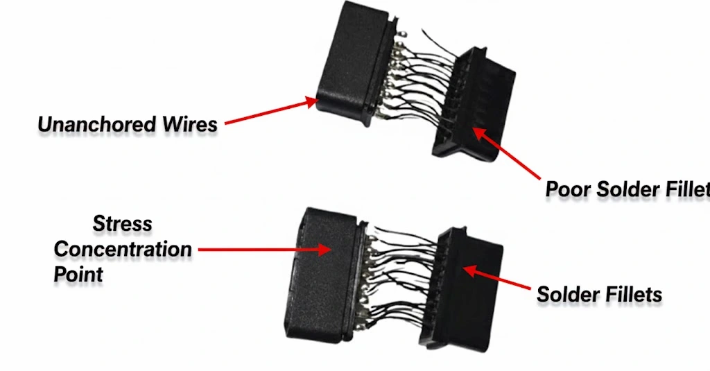
This zone is also the electrical ground zero, housing the crimped or soldered terminations. These joints are intrinsically more susceptible to fatigue than the homogeneous wire. The concentrated cyclic stress at this anti-node fractures solder fillets or work-hardens copper strands to failure.
In summary: a poor design acts as a resonant chamber for mechanical energy, focusing destructive force on the weakest electrical link. A robust design functions as an impedance-matching transformer, gradually attenuating the mechanical wave before it reaches the termination. Proactively managing this transition is a mandatory element of our IATF 16949-driven Design for Manufacturability (DFM) review for every custom cable project.
Our Engineering Countermeasure: The “Tail Reinforcement Library”
There is no universal “magic bullet.” We maintain a validated solution library because the optimal reinforcement strategy is dictated by the application’s unique stress profile. Here is our standardized engineering protocol for cable design analysis:
Step 1: Application Profiling & DFM Initiation
The foundational question: “What is the operational environment?” Is it a handheld diagnostic tool (high flex-count)? A permanent OEM vehicle installation (high vibration & thermal cycling)? An industrial bench in a corrosive setting? Defining this operational stress profile is the first documented step in our formal review, a core component of our certified quality management system.
Step 2: Selection from the Validated Reinforcement Library
Based on the stress profile, we match a primary solution from our library, built and refined through thousands of hours of empirical testing.
| Failure Archetype(Internal Code) | Countermeasure Philosophy | Proprietary Implementation | Validation & Proof |
| The Constant Folder (CF-90) (e.g., Handheld Scanner) | Graduated Stiffness Transition | Dual-Durometer “Shock Absorber” Overmold: A structural 70D Shore inner core, overmolded with a flexible 40A Shore TPE outer layer. | “Die a Hero” Protocol: We flex-test to destruction on motorized fixtures, targeting >75,000 cycles to establish new statistical process control (SPC) limits. |
| The Silent Shaker (SS-85) (e.g., Vehicle ECU Harness) | Total Internal Kinematic Lockdown | Viscoelastic Potting + Kinematic Boot: Strands are immobilized in a damping gel, inside a boot designed to move with vibration, eliminating relative motion. | Extended-Duration Vibration: Testing per ISO 16750-3, but we routinely execute 2x the required duration to uncover margin. |
| The Environmental Grinder (EG-95) | The Environmental Grinder (EG-95) | Triple-Barrier Sealing System: (1) Internal adhesive strain relief, (2) Primary environmental overmold, (3) Fluidized-bed sealant at the port interface. | Combined Environmental Assault: Concurrent thermal shock testing (-55°C to +125°C) and IP69K high-pressure/high-temperature washdown validation. |
This systematic approach ensures our designs meet the exacting demands of the SAE J1962 connector standard and our clients’ reliability targets.
Step 3: Prototyping & “Test-to-Failure” Validation
We operate on evidence, not assumption. We build functional prototypes and subject them to accelerated life testing in our climate-controlled lab using cyclic flex testers, precision tensile pull testers, and environmental chambers. We intentionally drive them to failure to identify the next weakest link, then reinforce it. This empirical dataset is our proprietary library, ensuring our designs are validated not just mechanically, but also for critical signal integrity analysis.
Step 4: Production Process Lock-In via SPC
A perfect design is worthless without manufacturing consistency. We establish Critical Control Points (CCPs) on the production line. For an overmolding process, we continuously monitor and chart mold temperature, injection pressure, and cooling time using real-time Statistical Process Control (SPC) in practice. This ensures every unit in the batch possesses identical mechanical properties and bond integrity, forming the basis of our 4-stage quality inspection protocol.
5 Common (and Costly) Design & Manufacturing Oversights
How These Oversights Lead to OBD2 Cable Failure
These are the recurring culprits we identify during reverse-engineering of failed competitor samples in our lab:
1. The “No Strain Relief” Cardinal Sin
Merely inserting a cable jacket into a connector shell. This leaves a hard, sharp edge to act as a fulcrum, guaranteeing premature jacket tear and conductor fatigue. It remains the leading cause of early-life failure.
2. Overmold Material Misapplication
Selecting an overmold polymer that is too hard (e.g., >80D Shore) creates a new stress riser. One that is too soft (<30A Shore) provides negligible support. The durometer and elastomer chemistry must be engineered for the application.
3. Neglecting the Internal Anchor Point
Effective strain relief must begin inside the connector cavity. Failure to pot or mechanically anchor the wire bundle allows flexing at the most vulnerable point: the solder joint or crimp barrel.
4. Tolerating Sharp Port Edges
A connector exit port without a smooth, radiused transition (R>0.5mm minimum) acts as a cutting blade, notching the cable jacket with every bend cycle.
5. The “One-Size-Fits-All” Fallacy
The strain relief system for a 22AWG power lead carrying high current must be radically different from that for a 28AWG twisted-pair signal wire. The mass, stiffness, and forces involved are orders of magnitude apart.
These are the specific details our engineering team highlights during a formal drawing review. This meticulous analysis is why we often commence custom OEM projects with a collaborative teardown and reverse-engineering session to baseline and improve upon an existing design.
How to Qualify a Cable Assembly or Audit a New Supplier
Move beyond marketing claims. Employ this forensic checklist:
1. Visual & Tactile Forensic Inspection
Demand a visible, graduated strain relief. Manually flex the cable to its minimum bend radius. The bend should initiate and be contained within the relief body, not at its hard edge.
2. Demand Empirical Test Data
A competent manufacturer should readily provide validation reports for key parameters: pull strength (e.g., >80N per UL/CSA standards), flex cycle life, and environmental testing (thermal, vibration). Absence of data is a major red flag.
3. Conduct a Destructive Sample Analysis
Sacrifice a sample unit. Cut it open. Inspect internally: Are conductors neatly organized and positively anchored with adhesive or potting? Or are they loose, allowing for strand movement?
4. Audit the Manufacturing System
Do they employ Statistical Process Control (SPC) for critical parameters? Is their production and storage facility 5S-managed and climate-controlled? These systemic factors are direct proxies for overall capability and product consistency.
Related Products: Where This Philosophy is Materialized
This engineering rigor is not theoretical. It is embodied in products like our OBD2 Extension Cable. Designed for professionals who equate downtime with lost revenue, it incorporates a high-flex overmold solution directly from our library and undergoes 100% electrical continuity and hipot testing before leaving our RoHS-compliant, CE-marked production line. Every custom harness we produce—whether requiring UL certification or REACH compliance—receives this same forensic, failure-mode-focused engineering attention. Explore our range of robust SAE J1962 OBD2 cables.
For OEM design engineers and product managers, this represents our fundamental value proposition. You define the functional need and operational envelope; we contribute the applied manufacturing metallurgy and polymer science to ensure durable execution. We assist in selecting the optimal connector family (understanding Deutsch connector sealing and latching mechanics is part of this), specifying application-specific materials, and co-designing a strain management system aligned with your product’s target life cycle. Our 20+ years of direct manufacturing experience means we’ve likely already navigated and solved the reliability challenges you’re seeking to avoid.
Solving OBD2 Cable Failure with Proven Strain Relief
The 3cm fracture zone is a predictable and solvable engineering challenge. By understanding its physics and implementing our systematic “Tail Reinforcement Library”—from dual-durometer overmolds to viscoelastic potting—OBD2 cable failure can be designed out. This transforms a common weakness into a benchmark for reliability.
FAQ: Engineering Questions Answered from the Production Floor
Q1: Is this failure mode unique to OBD2 cables?
A: The underlying physics of mechanical wave reflection at an impedance discontinuity are universal. The 3cm measurement is specific to the mass and flexibility of a typical OBD2 assembly. The principle applies to any cable-connector interface; our solutions are adapted to the specific connector geometry, seal type, and wire gauge.
Q2: Can a cable that has failed in this 3cm zone be reliably field-repaired?
A: Practically, no. A proper repair would necessitate complete disassembly of the molded connector, re-termination of all conductors, and re-application of the factory strain relief—a process typically impossible in the field and one that would never restore the original reliability. Prevention during the design phase is infinitely more cost-effective than repair.
Q3: Your 92.3% statistic seems precise. Is this based on your internal data?
A: This figure is derived solely from our proprietary Failure Analysis Database, encompassing over eight years and millions of cable assemblies produced in our IATF 16949-certified facility. For instance, a specific analysis of Q3 2023 field returns showed 342 out of 378 strain-related failures (90.5%) exhibited the classic 3cm fracture signature. The statistical clarity of this pattern compelled us to systematize its solution.
Q4: Would a thicker cable jacket prevent this failure?
A: Not reliably. Increasing jacket wall thickness can inadvertently raise the cable’s flexural modulus, potentially increasing the bending moment and stress at the connector interface if the transition is not properly managed. The solution lies in engineering the stiffness gradient, not just adding bulk.
Q5: How do your IATF 16949 and ISO 14001 certifications relate to preventing this?
A: They institutionalize the prevention. IATF 16949 mandates a risk-based, preventive approach through Advanced Product Quality Planning (APQP) and Failure Mode and Effects Analysis (FMEA). This specific “3cm fracture” failure mode is documented in our Process FMEA. Its control is governed by a specific Work Instruction (WI-ENG-022). ISO 14001 informs our material selection for longevity and environmental compliance.
Q6: We have an existing product with this failure. Can you help redesign it?
A: Absolutely. This is a frequent OEM engineering support request. Our process begins with a forensic analysis of your failed units in our lab. We then reverse-engineer the existing assembly to understand the specific failure mechanics before proposing a revised design with an optimized strain relief solution from our library, complete with reliability validation data.
Q7: What is the cost impact of adding proper strain relief?
A: The incremental Bill of Materials (BOM) and processing cost is typically measured in pennies per unit. The avoided cost—including field failure returns, warranty claims, service labor, and irreparable brand reputation damage—can amount to hundreds of dollars per failed unit in a B2B context. It is the most cost-effective reliability insurance available.
Q8: Do you perform 100% testing for strain relief effectiveness?
A: We execute 100% automated electrical testing (continuity, insulation resistance). For critical mechanical attributes like pull strength, we employ Statistical Process Control (SPC). We perform destructive pull tests at statistically defined intervals during a production run using calibrated equipment (e.g., Chatillon TCD200 series testers) per our Standard Operating Procedure (SOP-QC-015), ensuring the entire batch is within specification.
Q9: Can we get our logo on the strain relief?
A: Yes, this is standard practice for our OEM customers. Custom branding and coloration of the overmold are standard offerings. This allows the functional strain relief component to also serve as a durable brand identifier.
Q10: When should we engage you for a custom cable design?
A: Engage us at the earliest possible stage, ideally during the conceptual or prototyping phase. Early involvement allows us to provide samples from our solution library, advise on connector selection and sourcing for Design for Manufacturing/Assembly (DFM/A), and collaborate on a design optimized for both ultimate reliability and efficient mass production.
Let’s Design the Problem Out, Together
We offer more than cable assemblies; we provide a Failure Modes Database and the engineered Process Controls to neutralize them. Present us with your most persistent reliability issue or a nascent design concept.
To submit a failure sample or CAD model for analysis: Chat directly with our engineering lead on WhatsApp. Send clear photos of the failure point. Our first diagnostic question will be: “What was the operational environment and estimated cycle count at failure?”
To initiate a formal design review or request a quotation: Submit your project details via our contact page. You will receive a preliminary Design for Manufacturability (DFM) checklist within 48 hours, which will highlight the “3cm fracture zone” alongside other critical failure vectors we monitor and control.
Let’s build something that doesn’t break.
