

Look, I’ll be honest with you. When I started in this industry back in the late 90s, we didn’t have the luxury of CAN bus analyzers plugging into a laptop every five minutes. We had a multimeter, a breakout box, and if we were lucky, a service manual that wasn’t covered in diesel grease. The network we fought with daily was the J1708 .
I’m bringing this up because last month, I got a call from a fleet manager in Texas. They had a 2000 model year tractor—one of those old workhorses they refuse to retire because it starts every morning. The 2023 model next to it has been in the shop three times this month. The complaint? The dash had gone completely dark on the data side. The engine ran fine, but the tach was dead, the transmission wasn’t talking to the logger, and their JPRO tool kept timing out when trying to connect.
After three hours of head-scratching from their young technician (who had only ever worked on J1939), I walked them through a J1708 diagnostic procedure over the phone. We had it fixed in 40 minutes. It wasn’t magic. It was just understanding how this old protocol actually behaves on the wire.
So, let’s talk about J1708. Not from a textbook, but from the perspective of someone who has had to lie under a dashboard in July with sweat dripping into his eyes, trying to figure out why a perfectly good truck won’t talk to a scanner.
What Exactly Are We Dealing With? (The 9600 Baud Reality)
Before we start throwing parts at a truck, we need to understand what J1708 is physically. SAE J1708 defines the physical layer of the network. Think of it as the plumbing. The data that flows through these pipes is usually formatted by the J1587 protocol .
Here is the technical reality I’ve confirmed through two decades of building these cables on our ISO 9001 floor:
Speed: 9600 bits per second. If J1939 is a fire hose of data, J1708 is a drinking fountain. You can stand there and watch each bit trickle through. I’ve had enough time waiting for J1708 scans to drink an entire cup of coffee—sometimes two.
Medium: Two-wire twisted pair—18 gauge if the factory did their job right. Those twists per inch aren’t decorative. They’re there to cancel the noise from the starter cable running parallel six inches away, so your data doesn’t vanish every time the driver hits the key. This is classic RS-485 behavior, a standard known for handling electrically noisy environments through balanced signaling .
Length: Can run up to 40 meters (about 130 feet). Push it past that and the signal blurs into noise. I’ve seen guys add 50 feet of cheap extension cable and wonder why their data looks like a bad radio station.
Message Length: Usually capped at 21 bytes—unless the truck is sitting still. That’s one of those J1708 quirks that makes no sense until you realize the standard was written back when engineers thought trucks would never need to send more than 21 characters while rolling down the highway. I’ve watched techs chase “intermittent faults” for hours because they didn’t know the message length changes when the wheels stop turning .
Hardware: Based on RS-485 transceivers, but configured for “open collector” operation . Plain English: the lines are normally pulled high, and the ECUs pull them low to transmit. When an ECU dies, it sometimes gets stuck in the “pulling low” position and takes the whole network down with it. I’ve seen a $50 ABS module take out a $2,000 gateway because of this.
Why does this matter to you? Because when this network fails, it fails in specific ways. It usually doesn’t just stop the engine. It confuses the technician. It creates symptoms that make you question whether you know anything about trucks at all.
The Four Ways J1708 Dies (And How to Spot Them)
In my 20+ years on the shop floor and now overseeing our ISO 9001 , ISO 14001 , and IATF 16949 certified production line, I’ve seen the same four failure modes pop up repeatedly. Here is how to identify them without guessing.
1. The “Silent Bus” (No Communication)
The Symptom: You plug in your diagnostic tool. It powers up. But it says “No Data” or “Communication Error.” The engine runs, but you can’t see RPM or faults. The dash might be working, but the data link is dead.
The Technical Reality: You have a physical break in the bus, or a module has failed short, pulling the entire network voltage down. Somewhere, a wire is open, or an ECU is holding the line low and refusing to let go.
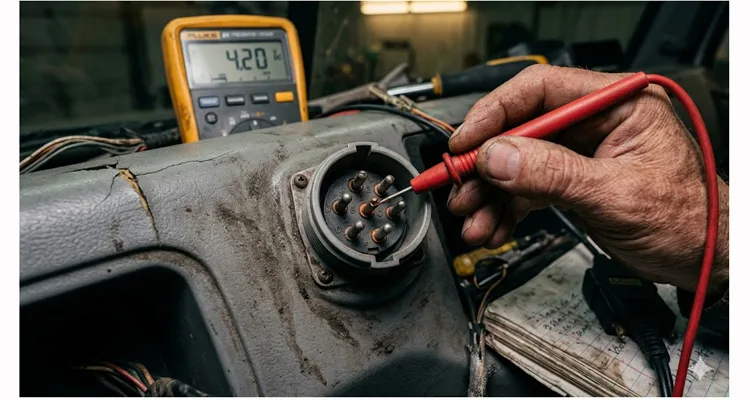
How to confirm it: Grab your multimeter—not the cheap one from the auto parts store, the one you actually trust. Probe between the A and B pins on the 6-pin Deutsch diagnostic connector. (Or pins 3 and 10 on the 9-pin J1939 connector, which also carries J1708.)
- J1708 A (+): Should sit between 3.5V and 4.5V relative to ground. Think of it as the “resting voltage.”
- J1708 B (-): Should show 0.5V to 1.5V. This is the return path.
- Differential Voltage: The difference between them should land somewhere around 2V to 3V.
Here’s a trap I’ve watched good technicians fall into: If you see both lines sitting at 2.5V, you’re not looking at J1708. You’re looking at J1939. CAN bus lives at 2.5V. J1708 needs that spread. 2.5V on both pins means you’re probing the wrong network, and the J1708 transceivers are either powered down or dead entirely. I’ve seen three ECMs replaced because of this mistake.
2. The “Babbling Node”
The Symptom: Communication is intermittent. Sometimes you get data, sometimes you don’t. When you do get data, it looks like garbage or the tool freezes. You might see RPM for five seconds, then nothing for ten, then a flash of nonsense characters.
The Technical Reality: One ECU on the network has failed internally. It might be transmitting constantly (babbling) or sending corrupted data that crashes the bus. Because J1708 uses a priority system based on the Message ID (MID) , a faulty module can hog the line and refuse to let anyone else speak .
How to confirm it: Start pulling modules. Not randomly—follow the vehicle architecture. Unplug the ABS controller first. In my experience, those Bendix and Wabco units from the early 2000s are the usual suspects. Moisture seeps past the connector seals, the board starts corroding, and suddenly the ABS is screaming nonsense onto the bus 24/7. Check communication. Still dead? Unplug the transmission ECU. Then the instrument cluster. Then, finally, the ECM—because the engine computer is rarely the problem, but you have to rule it out.
When the data stream snaps back to life after you unplug a module, you’ve found your chatterbox. I had a Freightliner years ago where the ABS module was transmitting so much garbage that the network looked like a teletype machine having a seizure. One unplug later, clean as a whistle.
3. The “Invisible Short”
The Symptom: Everything worked fine yesterday. Today, the dash is dead. It rained last night. Or the truck went through a car wash. Or the driver hit a deep puddle.
The Technical Reality: Corrosion. J1708 connectors (especially the old 6-pin Deutsch) are usually weather-resistant, but age and vibration can wear down seals. Water ingress creates a high-resistance path to ground or between the wires. It’s not a dead short—it’s a leaky one, and it only shows up when things get wet.
How to confirm it:
- Unplug the batteries. I cannot stress this enough—J1708 runs on 5V logic, and if you short something while the system is live, you can fry multiple ECUs in a split second.
- Set your meter to resistance. Probe between J1708 A and chassis ground. You want to see infinite resistance—OL, open line, whatever your meter calls it. If you see anything under 1k Ohm, you’ve got moisture somewhere. I’ve sat in parking lots with a heat gun and a cup of coffee, watching the resistance climb from 300 Ohms to 50k Ohms as the water evaporated from a Deutsch connector. When it hits infinity, plug the batteries back in and see if the truck talks.
- While you’re at it, check between J1708 A and B. A dead short (0-5 Ohms) means pinched wires—somewhere, those two conductors are touching. But the invisible short, the one that drives you crazy, reads somewhere between 10 and 500 Ohms. It’s not enough to blow anything. It’s just enough to drag the voltage down so the bus can’t decide if it’s high or low.
4. The “Gateway Headache”
The Symptom: The engine runs, but the telematics unit (GPS/ELD) isn’t reporting mileage or RPM. The J1939 network looks perfect. You can talk to the engine through the 9-pin connector, but the fleet tracking system shows the truck parked in the middle of a field.
The Technical Reality: In modern trucks, J1708 and J1939 coexist. They talk to each other through a Gateway Module (often the instrument cluster or a body controller). The J1708 physical wires might be fine, but the gateway has crashed or the software is hung. The data is there, but it’s not making it across the bridge. When you encounter this, you often need a physical bridge as well, like a Cummins J1708 to J1939 Diagnostic Cable , to ensure your diagnostic tool can communicate with both networks simultaneously.
How to confirm it: Try the simplest test first: cycle the key. Turn it off, count to thirty, turn it back on. If the telematics box suddenly starts reporting mileage again, the hardware is fine—the gateway just went to sleep and forgot to wake up. I’ve seen this on Internationals and early Cascadias where the body controller’s software has a memory leak. Runs fine for three days, then the J1708 bridge collapses. A restart buys you another three days. The permanent fix is a firmware flash or, if the truck is out of warranty, a replacement cluster. But at least now you know it’s not a wiring issue.
Step-by-Step: Resurrecting a Dead J1708 Bus
Let’s walk through the scenario I mentioned at the start. Here is the exact procedure we used to fix that 1999 Freightliner.
Tools Needed:
- Digital Multimeter (DMM) with good leads. Cheap meters lie. Spend the money on a Fluke or something equivalent. I’ve seen $20 meters read 5V when there’s only 3V on the line.
- Breakout Box (or just some back-probing pins). I use a set of T-pins from a sewing kit—they’re sharp, they fit into the back of Deutsch connectors, and they cost about two dollars.
- The vehicle wiring diagram (Yes, you need it. Don’t guess the pinouts). I don’t care how many trucks you’ve worked on—every OEM does something slightly different with pin assignments. Freightliner pins things one way, Kenworth another.
Step 1: Visual Triage
Stop. Don’t grab the meter yet. Look at the 6-pin Deutsch connector. Are the pins pushed back? Is there green fuzz (corrosion) visible? I once spent an hour tracing a “network fault” only to realize the customer had plugged a 12v test light into the datalink port and bent three pins sideways. Fix the physical damage first. Deutsch pins are designed to be removed and replaced—if one is pushed back, use the proper extraction tool and reseat it.
Step 2: Voltage Check (Key ON)
Probe the back of the connector (or use your breakout box).
- Pin C (usually J1708 + ): Look for 3.5V – 4.5V.
- Pin D (usually J1708 – ): Look for 0.5V – 1.5V.
If these voltages are off, you have a power supply issue to the transceivers or a short. If Pin C reads a clean 5V and Pin D reads 0V, you’ve got an open circuit. The pull-up resistors inside the ECUs are doing their job, but there’s no path to ground—meaning somewhere, a wire is broken or a connector is unplugged. The bus is powered up and waiting, but nobody’s home.
Step 3: Resistance Check (Key OFF, Batteries Disconnected)
Measure resistance between Pin C and Pin D. Forget everything you know about CAN bus termination. J1708 doesn’t use 120-ohm terminating resistors at the ends of the line. The resistance you’re measuring here is the parallel combination of all the bias networks inside every ECU on the bus. More ECUs online means lower resistance. A healthy bus with a full set of modules usually reads somewhere between 60 and 120 ohms. If you see less than 50 ohms, you’ve got a short—the wires are touching somewhere they shouldn’t. If you see zero, or close to it, that’s a dead short. Somewhere, insulation has failed and the two conductors are welded together.
Step 4: The Isolation Game
If voltages are off, or resistance is zero, start isolating.
- Locate the Engine ECM connector.
- Unplug it.
- Check your resistance/voltage at the diagnostic port again.
If the readings improve, the ECM was the problem. If not, move to the next module. This is tedious, but it’s the only way to find the bad actor without specialized equipment. I’ve spent entire afternoons playing this game, but it beats replacing parts randomly.
The “Aha!” Moment from Texas:
When we unplugged the transmission ECU on that 1999 truck, the voltages at the diagnostic port snapped back to normal (4.2V and 1.2V). We had found the “babbling node.” The transmission ECU had an internal short in its RS-485 transceiver. Replacing the ECU (or in their case, sending the old one out for rebuild) fixed the network instantly. The young technician on the other end of the phone said, “I can’t believe it was that simple.” I told him, “It’s always simple once you know where to look. The hard part is knowing where to look.”
Five Common Mistakes Even Veteran Techs Make
We’ve all been guilty of these. If you avoid these five, you’ll save hours.
- Confusing J1708 with J1939 Voltages. As mentioned earlier, if you see 2.5V on both lines, you are measuring the CAN bus, not J1708. Don’t try to diagnose J1708 faults using J1939 voltage specs. I’ve seen guys replace three ECMs because they kept reading 2.5V and thought the network was dead—turns out they were probing the wrong pins.
- Splicing with the Wrong Wire. I’ve watched a guy spend two hours diagnosing a “ghost in the machine” only to find the previous repair had used lamp cord—the ribbed insulation kind so you know which wire is which. Looked fine sitting still. But the first time that truck hit the starter, the whole data stream turned to static. The starter motor draw creates a magnetic field that wraps around unshielded wire like a python. If your repair isn’t twisted pair—real twisted pair, not just two wires running parallel—you haven’t fixed anything. You’ve just delayed the failure. This is exactly the kind of problem we address in our guide on Field Guide to CAN Bus EMI Shielding , where we detail how electromagnetic interference couples onto data lines. The differential signaling used by RS-485 is designed to reject this noise, but only if the pair is properly twisted .
- Forgetting the 12-Bit Break. The J1708 protocol synchronizes by detecting 12 consecutive logic “high” bits (basically 1.25ms of silence). If you have a noisy network (due to a failing alternator or bad ground), the bus never sees that silence. It can’t synchronize, so it never receives data correctly. Check your grounds. I’ve fixed more “network problems” by tightening a battery ground cable than by any other method.
- Assuming the 9-Pin Connector is Only J1939. Pull out your 9-pin to 6-pin adapter and look at the pins. Really look at them. If you bought that adapter from Amazon for twelve dollars, I can almost guarantee the manufacturer left the J1708 pins empty. They save thirty cents per unit by not populating pins E and F, and you spend three hours wondering why your scanner won’t talk to the transmission. I keep a stack of adapters on my bench that I’ve cut open just to show customers—the cheap ones have empty holes where pins should be. A properly built adapter, like a Green 9pin J1939 to 6pin J1708 Adapter , has all pins present and correctly terminated to ensure reliable communication.
- Ignoring the Checksum. Every J1708 message ends with a checksum—a mathematical fingerprint of everything that came before it . If you’re looking at raw data and the checksum doesn’t match, the network is screaming at you: “Something corrupted this message!” Don’t blame the tool. Don’t blame the software. The checksum error means the data got mangled somewhere between the transmitting ECU and your screen. That’s a wiring problem, a noise problem, or a ground problem. The checksum is your canary in the coal mine. When it dies, pay attention.
How Do You Know It’s Actually Fixed?
You cleared the code. The dash lights are back. The technician is packing up. Are you done?
Not yet. Perform these three final checks:
The Key Cycle Test: Turn the ignition off. Wait 30 seconds. Turn it back on. Does the check engine light flash properly? Does the diagnostic tool reconnect instantly without timing out? Some faults only show up on a cold start—if the network comes up clean after a full power cycle, you’re probably good.
The Wiggle Test: Start the engine. Let it idle. Grab the harness right where you made your repair—not gently, either. Flex it. Twist it. Pull on it like you’re trying to break it. (You probably won’t, but if you do, you’ll know the repair wasn’t strong enough.) Watch the dash. Watch your scanner. If the data doesn’t flicker, if the dash doesn’t blink, you’ve got a solid mechanical connection. If the data drops out when you wiggle it, you’ve got a broken wire hiding inside the insulation or a crimp that wasn’t quite right. Cut it out and start over.
The Live Data Check: Scroll through a few PIDs on your scanner (like RPM, Oil Pressure, Coolant Temp). Do they update smoothly? If they freeze or jump erratically, you might still have noise on the line. Watch the values for a full minute—intermittent problems often show up as a single frozen frame or a spike to zero. I’ve seen coolant temp readings jump from 180 to 240 in a heartbeat because of a bad ground.
Building a Better Link: The Hardware Perspective
Over the years, watching these failures happen in the field has directly influenced how we design and manufacture our cables here at the factory. We hold ISO 9001 , ISO 14001 , and IATF 16949 certifications for a reason—because we know that in a J1708 network, the cable is not just a piece of wire; it’s a precision component.
When we build a diagnostic cable or an extension harness for J1708 applications, we obsess over the details you can’t see:
- Twist Rate: We spec 12 to 14 twists per foot on every J1708 cable we build. Not 10. Not 15. 12 to 14. I’ve had engineers ask why we’re so picky. Here’s why: impedance is a function of twist rate. Too few twists, and the impedance drifts high—the signal reflects back onto itself. Too many twists, and you add capacitance that rounds off the edges of your digital pulses. At 9600 baud, you’ve got some margin, but why gamble? We measure twist rate on every production run because I’ve seen what happens when a cable becomes an antenna instead of a transmission line. The truck runs fine, but the data looks like a bad radio station.
- Shielding: Our cables use a foil shield with a drain wire. In a high-RFI environment like a Class 8 truck, that shield is the only thing keeping your 9600 baud signal readable. The drain wire needs to be grounded at exactly one end—usually the diagnostic connector side—to avoid creating a ground loop. For a deeper dive into why this matters, read our post on Field Guide to CAN Bus EMI Shielding , which covers the physics of noise coupling in industrial settings.
- Pin Contact: We use gold-plated pins in our Deutsch connectors. Standard tin plating can oxidize over time, creating that “intermittent” fault that drives you crazy. Gold doesn’t oxidize. It costs more, but so does a tow truck. I’ve seen tin pins fail after two years in a humid environment; gold pins last decades.
- Strain Relief: A 90-degree molded strain relief isn’t just for looks. It prevents the technician’s boot from snapping the connector off the diagnostic port. Straight connectors put leverage on the pins every time the cable gets bumped. The 90-degree design keeps the force aligned with the connector axis. We’ve tested this to 10,000 flex cycles.
We run a 4-step quality inspection on every batch, and our assembly area follows 5S management with climate-controlled storage for raw materials. It sounds like overkill for a simple cable, but when that cable is the only thing between a fleet manager and a $3,000 diagnostic bill, the quality matters. We’ve had customers tell us they threw away every other brand of adapter cable after trying ours—not because we asked them to, but because ours worked every time and the others didn’t.
Frequently Asked Questions from the Shop Floor
Here are some questions I get asked regularly by engineers and fleet managers who are tired of fighting with legacy networks.
1. Can I just ignore the J1708 network if the truck has J1939?
Technically, yes, the engine will run. But if you ignore it, you lose data from the ABS controller, the transmission (if it’s an older model), and the instrumentation cluster. You also lose the ability to calibrate certain parameters with older diagnostic software. The two networks usually work in tandem. On most trucks built between 2000 and 2010, the J1708 network handles the legacy devices while J1939 handles the high-speed engine control.
I had a fleet manager in Ohio try this once—figured he’d save money by deleting the J1708 gateway. Three weeks later, his drivers started reporting “check engine” lights that wouldn’t clear because the ABS faults were trapped on the J1708 side and never made it to the J1939 bus. He spent more on diagnostic time than the gateway would have cost.
2. What is the maximum length of a J1708 cable?
The standard specifies up to 40 meters (130 feet) . In practice, if you are extending a diagnostic line, keep it as short as possible. Every extra foot adds capacitance and potential for noise. I’ve seen people run 50-foot extension cables so they can sit in the cab with the laptop while the truck is in the bay—it usually works, but if you’re having intermittent issues, try a shorter cable first.
The spec says 40 meters. In practice, I’ve seen 50-foot extension cables work fine in a clean shop environment. But put that same cable on a truck with a marginal alternator and a weak battery ground, and the extra length becomes an antenna. I keep a 25-foot cable in my truck and a 6-foot cable in my box. I use the short one first.
3. Why does my diagnostic tool only work sometimes?
Ninety percent of the time, this is a connector issue. Either the pins in the dash socket are worn out (losing tension) or the cable you are using has a broken wire inside the insulation that makes contact only when held in a certain position. Try wiggling the connector while watching the data stream—if it comes and goes, you’ve found your problem.
I carry a magnifying glass in my tool box specifically for this. Nine times out of ten, I’ll find one pin in the dash socket that’s slightly recessed—pushed back by someone who jammed a connector in sideways. A dental pick can usually coax it back into position, but if the retention clip is broken, you’re looking at a socket replacement.
4. Is J1708 the same as RS-232?
No. RS-232 uses higher voltages (+/-12V) and is usually point-to-point. J1708 uses RS-485 style differential signaling (5V) and allows multiple nodes on the same wire pair . You cannot connect an RS-232 device directly to a J1708 bus without a converter. I’ve seen people try. It doesn’t end well—usually with smoke coming from somewhere.
5. How do I know if my custom harness needs shielding?
If you are running the cable inside the cab, unshielded twisted pair is often sufficient. If the cable runs outside the frame rail, near the starter, or near any high-current wiring, you absolutely need a shielded cable with the drain wire properly grounded. The alternator and starter generate massive electromagnetic fields—enough to induce several volts of noise in an unshielded cable. For a detailed breakdown of how to select and validate shielding in these environments, our article on Field Guide to CAN Bus EMI Shielding walks through the specific failure modes.
If you’re running the cable inside the cab, next to the driver’s seat, unshielded is usually fine. But if that cable has to go anywhere near the starter—and I mean within two feet of it—you need shielding. I watched a brand new telematics install fail repeatedly until we realized the installer had routed the cable along the frame rail, six inches from the starter cable. Every time the driver started the truck, the telematics unit would lose its mind for about three seconds. Relocated the cable with shielding, problem solved.
6. What is a “MID”?
A Message Identifier. It is the first byte of a J1587 message that tells you which module is talking (e.g., MID 128 is usually the Engine ECM, MID 130 is the Transmission) . When you’re looking at raw data, the MID is the first thing you see after the sync pattern. If you’re seeing MIDs that don’t match your vehicle configuration, you have a module misidentification issue or a corrupted data stream.
7. Can a bad ground cause J1708 errors?
Absolutely. If the ground reference between two modules is different by more than a couple of volts, the differential signaling on the J1708 bus can’t compensate, and you’ll get data errors. The bus expects both modules to be at roughly the same ground potential. A voltage drop of even 0.5V in a ground cable can push the signal outside the valid range. I’ve fixed more intermittent faults with a wire brush and a new ground lug than with any electronic wizardry.
8. Are your cables RoHS compliant?
Yes. All our materials meet RoHS, CE, and UL standards. We use a full-plastic design where appropriate to prevent corrosion and ensure environmental sealing. The RoHS requirement is becoming more common in commercial vehicle work, especially for fleets that operate across state lines or international borders.
9. Can I get a cable made with my company’s logo on it?
Yes, we offer full OEM customization. We can brand the cable with your logo, change the length, modify the color, or adjust the wire gauge (AWG) to meet your specific assembly requirements. We do this for several major telematics providers—they want their brand on the cable so their customers know it’s the approved part. A great example of this is our Cummins J1708 to J1939 Diagnostic Cable , which is often customized for fleet service providers.
10. Do you stock 6-pin Deutsch to 9-pin Deutsch adapters?
We do, but we also custom-build them. We have found that off-the-shelf adapters often use cheap aluminum connectors that corrode. We use high-quality brass or stainless steel shells on our custom runs to ensure longevity. If you’re buying adapters in bulk for a fleet, the price difference between aluminum and stainless steel is negligible compared to the cost of a roadside failure.
Still Wrestling with a Stubborn J1708 Issue?
If you are reading this because you’ve got a truck down and the diagnostic link just won’t cooperate, I get it. Sometimes the problem isn’t the protocol or the ECU—it’s the physical connection you’re holding in your hand. I’ve been there. It’s frustrating. You’ve checked everything twice, and the truck still won’t talk.
We’ve been building heavy-duty vehicle cabling for over 20 years. We know exactly how a cable should perform to keep that 9600 baud signal clean. We also know that sometimes you need something that doesn’t exist in any catalog—a specific length, a custom pinout, a connector that hasn’t been made in ten years.
If you need a reliable, custom-built J1708 diagnostic cable, extension, or adapter that won’t let you down mid-diagnosis, let’s talk. We can help you spec the right gauge, the right connector orientation, and the right shielding for your specific application. Tell us what truck you’re working on and what tool you’re using, and we’ll tell you exactly what cable you need.
Contact our engineering support team directly for a quote on OEM customizations, or message me on WhatsApp if you need help figuring out exactly what cable will solve your physical layer problem. I answer my own messages—no chatbots, no sales people reading from scripts.
Contact Us Page
Chat on WhatsApp
We don’t just sell cables; we help you engineer the connection.
